
Lightlink remote outlet

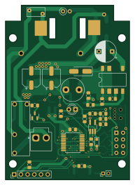
About the Lightlink remote outlet PCB
Lightlink remote outlet is an open source PIC PCB design by spstack, published on GitHub. It is a 2-layer board measuring 47 × 66 mm, with 59 components from 41 distinct parts.
Its main chip is the PIC16F18126, from the PIC family. Other key parts include the RFM69HCW, LNK304G, TPS56339DDC and TLV3201. By type, the board carries 18 resistors, 17 capacitors, 6 diodes, 5 ICs, 5 connectors and 2 switches.
It belongs with the iot & wireless and rf & radio designs in this gallery.
From the project
Code and PCB designs for a device that can link a switched power outlet to any other outlet remotely.
A way to remotely link power outlets! This is an idea taken from the "Switcheroo" device that allows taking an existing switched power outlet and linking it wirelessly with another outlet.
Basically, you can change the location of an outlet that is already hooked up to a switch. The device uses a simple 915MHz wireless transceiver so there's no wifi/bluetooth involved. You just select the channel you want to control and if any device on that channel is powered on or off, all of the devices on that channel will follow it.
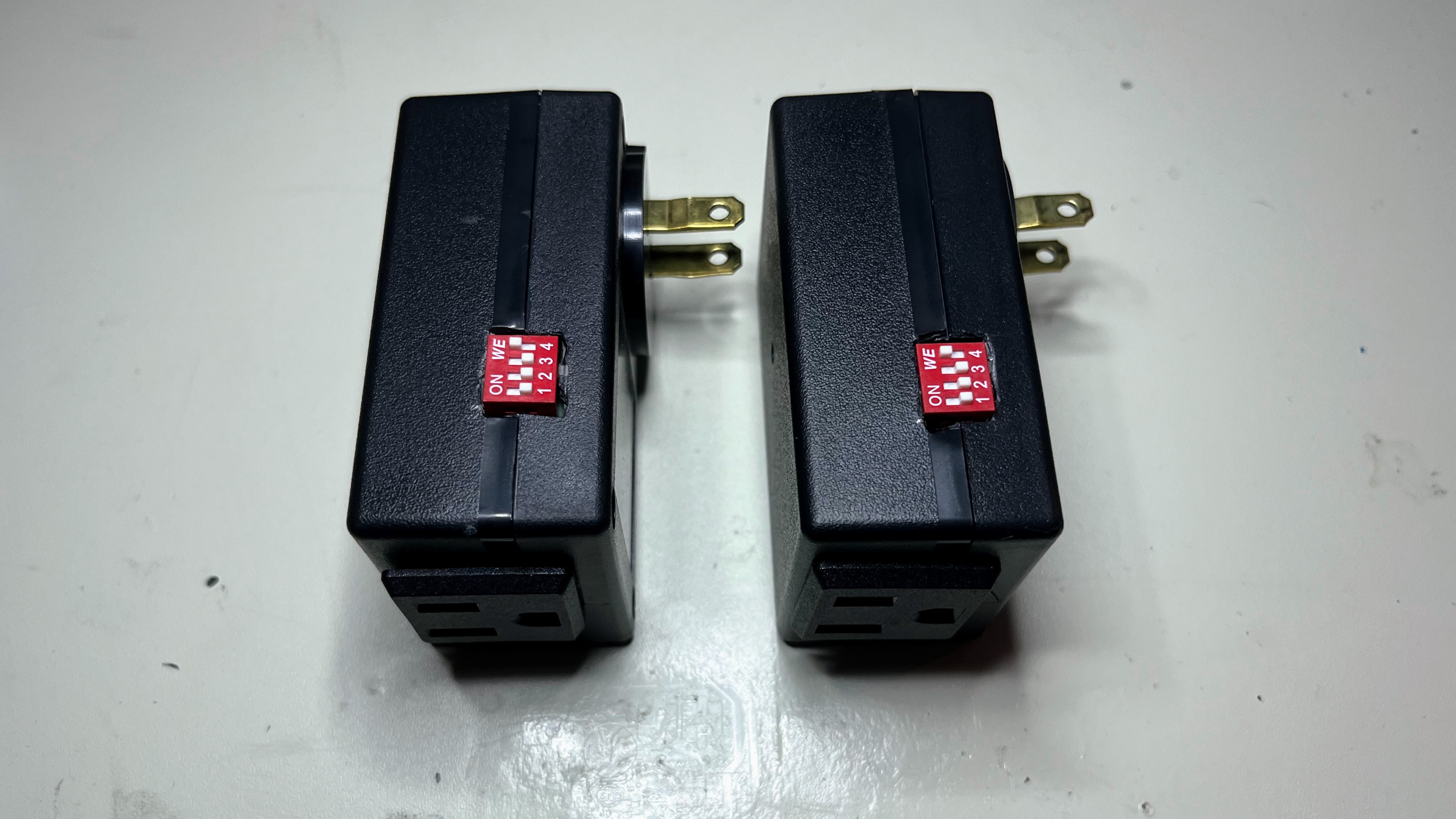
Main components on the Lightlink remote outlet
Lightlink remote outlet bill of materials (BOM)
59 components, 41 distinct parts — part numbers from the project's BOM.
| Qty | Part | Footprint | Refs |
|---|---|---|---|
| 1 | PIC16F18126 | SSOP-20_5.3x7.2mm_P0.65mm | U1 |
| 1 | RFM69HCW | HOPERF_RFM69HW | U2 |
| 1 | LNK304G | PowerIntegrations_SMD-8B | U3 |
| 1 | TPS56339DDC | SOT-23-6 | U4 |
| 1 | TLV3201 | TSOT-23-5_HandSoldering | U5 |
| 1 | Q_NMOS_DGS | SOT-23_FDV301 | Q1 |
| 1 | PIC Programming Header | PinHeader_1x06_P2.54mm_Vertical | J1 |
| 1 | Wire Antenna | PinHeader_1x02_P2.00mm_Vertical | J2 |
| 1 | Conn_WallSocket | JST_VH_B2P-VH-B_1x02_P3.96mm_Vertical | J3 |
| 2 | CONN_01X01_SOCKET Conn_01x01_Socket | conn_harwin_S1941-46R | J4, J5 |
| 1 | Fuse | fuseholder_20x5mm_keystone_4628 | F1 |
| 1 | Relay_SPST-NO | relay_SPST_NO_panasonic_ALDP112W | K1 |
| 1 | Varistor | RV_Disc_D7mm_W3.4mm_P5mm | RV1 |
| 1 | 418217270904A SW_DIP_x04 | DIP-8_SW_Horiz_Werth | SW1 |
| 1 | 228DD1S1AAFAMSC SW_MEC_5G_2LED | switch_right_angle_228DD1S1AAFAMSC | SW2 |
| 1 | D_Bridge_+A-A | SOPA-4 | D1 |
| 1 | ~ | D_SMA_Handsoldering | D2 |
| 2 | S1J-13-F | D_SMA_Handsoldering | D3, D6 |
| 1 | HLMP1700 RED LED | LED_D3.0mm | D4 |
| 1 | MM3Z2V7B 2.7V | D_SOD-323_HandSoldering | D5 |
Show 21 more
| Qty | Part | Footprint | Refs |
|---|---|---|---|
| 1 | 1MH 1mH | L_Radial_D8.7mm_P5.00mm_Fastron_07HCP | L1 |
| 1 | SRN5040-4R7M 4.7uH | L_Bourns_SRN5040 | L2 |
| 1 | 4.7UF 4.7uF | CP_Radial_D8.0mm_P5.00mm | C1 |
| 1 | 100NF 100nF | C_0805_2012Metric_Pad1.18x1.45mm_HandSolder | C2 |
| 2 | 10UF 10uF | C_0805_2012Metric_Pad1.18x1.45mm_HandSolder | C3, C5 |
| 2 | 100UF 100uF | CP_Elec_6.3x7.7 | C4, C9 |
| 8 | 0.1UF 0.1uF | C_0805_2012Metric_Pad1.18x1.45mm_HandSolder | C6, C7, C11, C12, C13, C14, C15, C16 |
| 2 | 22UF 22uF | C_0805_2012Metric_Pad1.18x1.45mm_HandSolder | C8, C10 |
| 1 | 0.1uF | C_0805_2012Metric_Pad1.18x1.45mm_HandSolder | C17 |
| 7 | 10K 10k | C_0805_2012Metric_Pad1.18x1.45mm_HandSolder | R1, R3, R4, R5, R6, R12, R14 |
| 1 | 31.6k | C_0805_2012Metric_Pad1.18x1.45mm_HandSolder | R2 |
| 1 | 13K 13k | C_0805_2012Metric_Pad1.18x1.45mm_HandSolder | R7 |
| 1 | 2.05K 2.05k | C_0805_2012Metric_Pad1.18x1.45mm_HandSolder | R8 |
| 1 | 20 | R_Axial_DIN0207_L6.3mm_D2.5mm_P2.54mm_Vertical | R9 |
| 1 | 3.3K 3.3k | C_0805_2012Metric_Pad1.18x1.45mm_HandSolder | R10 |
| 1 | 600 | C_0805_2012Metric_Pad1.18x1.45mm_HandSolder | R11 |
| 1 | 30 | C_0805_2012Metric_Pad1.18x1.45mm_HandSolder | R13 |
| 1 | 1k | C_0805_2012Metric_Pad1.18x1.45mm_HandSolder | R16 |
| 1 | 0 | C_0805_2012Metric_Pad1.18x1.45mm_HandSolder | R17 |
| 1 | 102K 102k | C_0805_2012Metric_Pad1.18x1.45mm_HandSolder | R18 |
| 1 | 34K 34k | C_0805_2012Metric_Pad1.18x1.45mm_HandSolder | R19 |
Lightlink remote outlet design files
The KiCad project lives in the spstack/lightlink-remote-outlet repository on GitHub; these links point at the commit this page was built from.
Lightlink remote outlet: common questions
What microcontroller does the Lightlink remote outlet use?
The Lightlink remote outlet is built around the PIC16F18126, from the PIC family.
How big is the Lightlink remote outlet PCB?
The Lightlink remote outlet measures 47 × 66 mm, has 2 copper layers and is 1.6 mm thick.
How many components are on the Lightlink remote outlet?
59 components, from 41 distinct parts, with part numbers taken from the project's own BOM. The full bill of materials is listed on this page.
Where can I download the Lightlink remote outlet design files?
From the spstack/lightlink-remote-outlet repository on GitHub, which has the KiCad layout, the schematic and the BOM; the links under Design files point to each one.
Can I use the Lightlink remote outlet design in my own project?
The repository has no license, so all rights stay with spstack. Use it as a reference, and ask the author before reusing the design.
Can I test firmware for the Lightlink remote outlet without the hardware?
Yes. HardLabs builds a simulation of the board from its netlist and BOM, so you can run and debug PIC firmware against it before you order a PCB.
Similar boards
 PIC
PICPslab hardware
fossasia
99 × 53.3 mm187 parts4LApache-2.01.7k PIC
PICMicro 8088
skiselev
152.4 × 101.6 mm71 partsGPL-3.0414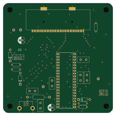 PIC
PICGB-CARTPP-DIY
Gekkio
100 × 100 mm22 parts2LCC-BY-4.0376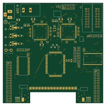 PIC
PICGB-BENCH-G1
100 × 100 mm98 parts4LCC-BY-4.0376 PIC
PICGB-MBCTEST
51.4 × 61 mm32 parts2LCC-BY-4.0376 PIC
PICGB-LIVE32
51.4 × 61 mm46 parts4LCC-BY-4.0376