
FIS-Display

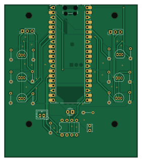
About the FIS-Display PCB
FIS-Display is an open source RP2040/RP2350 PCB design by Supermagnum, published on GitHub. It is a 2-layer board measuring 69.6 × 79.5 mm, with 27 components from 10 distinct parts.
Its main chip is the RaspberryPi_Pico, from the RP2040/RP2350 family. Other key parts include the MCP2561-H-P. By type, the board carries 14 resistors, 6 transistors, 3 connectors, 1 IC, 1 module and 1 diode.
It belongs with the iot & wireless, displays & leds and rf & radio designs in this gallery.
From the project
VW Passat B6 FIS Display — Hardware Connections and Software Protocols
- Disclaimer - What this project does - Gerber files and PCB manufacturing - Project structure - 1. System Overview - 2. Host Device — Navit with D-Bus - 2.1 Supported Platforms - 2.2 D-Bus Service Details - 2.3 Key Attributes to Subscribe To - 2.4 Navigation Status Values - 2.5 D-Bus Listener to Pico Bridge Script - 3. Serial Protocol (Host to Pico, 115200 baud) - 3.1 Eco mode icon (driver-break, D-Bus) - 4. Transport — USB CDC or Bluetooth SPP - USB CDC - Bluetooth SPP - 5. Hardware - 5.1 Controller — Raspberry Pi Pico 2 W - 5.2 The 3LB (Three-Line Bus) - 5.3 Level Shifting - 5.4 Instrument…
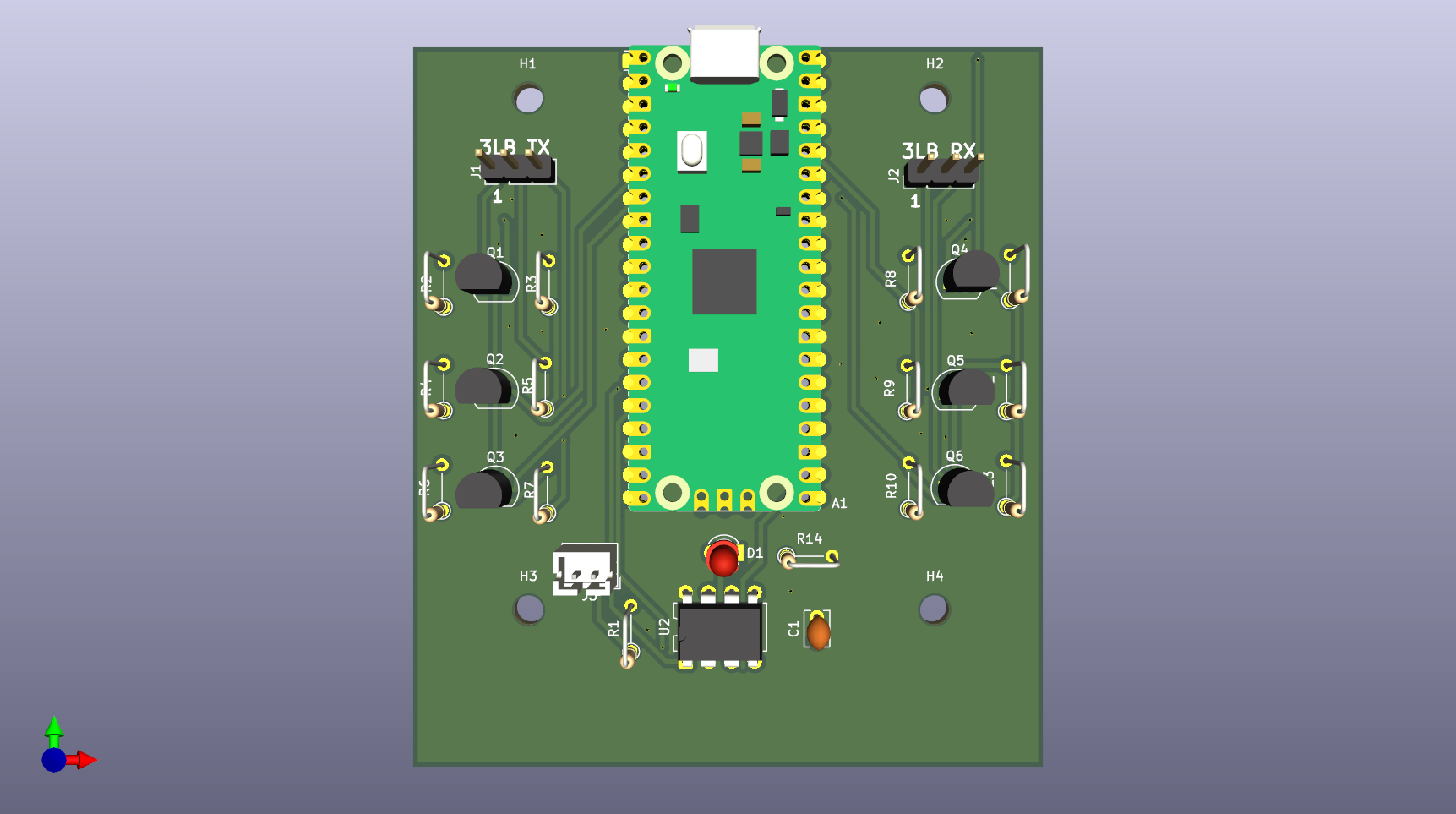
Main components on the FIS-Display
FIS-Display bill of materials (BOM)
27 components, 10 distinct parts.
| Qty | Part | Footprint | Refs |
|---|---|---|---|
| 1 | MCP2561-H-P | DIP-8_W7.62mm | U2 |
| 1 | RaspberryPi_Pico | RaspberryPi_Pico_Common_Unspecified | A1 |
| 6 | BS170 | TO-92_Inline | Q1, Q2, Q3, Q4, Q5, Q6 |
| 2 | Conn_01x03_Pin | PinHeader_1x03_P2.54mm_Vertical | J1, J2 |
| 1 | Conn_01x02_Socket | JST_PH_B2B-PH-K_1x02_P2.00mm_Vertical | J3 |
| 1 | LED | LED_D3.0mm | D1 |
| 1 | 4700pf | C_Disc_D3.8mm_W2.6mm_P2.50mm | C1 |
| 1 | 120 ohm | R_Axial_DIN0204_L3.6mm_D1.6mm_P5.08mm_Vertical | R1 |
| 12 | 2.2 kΩ | R_Axial_DIN0204_L3.6mm_D1.6mm_P5.08mm_Vertical | R2, R3, R4, R5, R6, R7, R8, R9 +4 |
| 1 | 100 | R_Axial_DIN0204_L3.6mm_D1.6mm_P5.08mm_Vertical | R14 |
FIS-Display design files
The KiCad project lives in the Supermagnum/FIS-Display repository on GitHub; these links point at the commit this page was built from.
FIS-Display: common questions
What microcontroller does the FIS-Display use?
The FIS-Display is built around the RaspberryPi_Pico, from the RP2040/RP2350 family.
How big is the FIS-Display PCB?
The FIS-Display measures 69.6 × 79.5 mm, has 2 copper layers and is 1.6 mm thick.
How many components are on the FIS-Display?
27 components, from 10 distinct parts. The full bill of materials is listed on this page.
Where can I download the FIS-Display design files?
From the Supermagnum/FIS-Display repository on GitHub, which has the KiCad layout and the schematic; the links under Design files point to each one.
Can I use the FIS-Display design in my own project?
The repository has no license, so all rights stay with Supermagnum. Use it as a reference, and ask the author before reusing the design.
Can I test firmware for the FIS-Display without the hardware?
Yes. HardLabs builds a simulation of the board from its netlist and BOM, so you can run and debug RP2040/RP2350 firmware against it before you order a PCB.
Similar boards
 RP2040/RP2350
Open Book Abridged Edition
joeycastillo
85 × 115 mm29 parts2LCC-BY-SA-4.08.1k RP2040/RP2350
Corne
foostan
277.2 × 107.5 mm164 parts2LCC-BY-4.07.7k RP2040/RP2350
Corne
277.2 × 107.5 mm164 parts2LCC-BY-4.07.7k RP2040/RP2350
LogicAnalyzer
gusmanb
57 × 55.2 mm6 parts2LGPL-3.05.0k RP2040/RP2350
Jitx design
55.5 × 65 mm26 parts4LGPL-3.05.0k RP2040/RP2350
Pro V2
kata0510
290.1 × 130 mm270 parts2LMIT2.3k