
Power supply

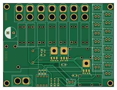
About the Power supply PCB
Power supply is an open source PCB design by syamei0, published on GitHub. It is a 2-layer board measuring 95 × 72 mm, with 60 components from 22 distinct parts.
Other key parts include the NJM7805SDL1, NJM2845DL1-33, 953-1C-12DG-1 and 134-1C-12DS. By type, the board carries 25 connectors, 10 diodes, 7 fuses, 6 resistors, 5 ICs and 5 capacitors.
It belongs with the power & battery designs in this gallery.
From the project
⚠注意⚠ リレーの逆起電力対策がされていません。 ダイオードを外付けして使用してください。
⚠注意⚠ リレーの逆起電力対策がされていません。 ダイオードを外付けして使用してください。
入力は12V 出力 12V×7(合計20Aまで) 5V×8(3.3V出力と合わせて合計1.5Aまで) 3.3V×8(合計800mAまで)
仕様 ・圧電スピーカーは0ピン ・CANはTXDが5ピン、RXDが4ピン ・JP3とJP4はcanの終端抵抗 ・上バー付の数字はPWM可 ・白抜き文字は書き込み中プルアップ
Main components on the Power supply
Power supply bill of materials (BOM)
60 components, 22 distinct parts — part numbers from the project's BOM.
| Qty | Part | Footprint | Refs |
|---|---|---|---|
| 1 | NJM7805SDL1 | TO-252-3_TabPin2 | U1 |
| 1 | NJM2845DL1-33 | TO-252-3_TabPin2 | U2 |
| 1 | 953-1C-12DG-1 | 953-1C-12DG-1 | U3 |
| 2 | 134-1C-12DS | 134-1C-12DS | U4, U5 |
| 1 | TTC014 | TO-252-3_TabPin2 | Q1 |
| 1 | XT60_IN | AMASS_XT60-M_1x02_P7.20mm_Vertical | J1 |
| 1 | Emergency Stop Switch | JST_XH_B2B-XH-A_1x02_P2.50mm_Vertical | J2 |
| 7 | XT60_OUT | AMASS_XT60-F_1x02_P7.20mm_Vertical | J3, J4, J5, J6, J7, J8, J25 |
| 8 | XH_OUT | JST_XH_B2B-XH-A_1x02_P2.50mm_Vertical | J9, J10, J11, J12, J13, J14, J15, J16 |
| 8 | XH_3.3V_OUT | JST_XH_B2B-XH-A_1x02_P2.50mm_Vertical | J17, J18, J19, J20, J21, J22, J23, J24 |
| 7 | Fuse | 3557-15_KEY | F1, F2, F3, F4, F5, F6, F7 |
| 1 | SW_DIP_X04 SW_DIP_x04 | KSD42 | SW1 |
| 3 | LED | LED_0603_1608Metric_Pad1.05x0.95mm_HandSolder | D1, D2, D3 |
| 1 | OSHR1608C1A | LED_0603_1608Metric_Pad1.05x0.95mm_HandSolder | D4 |
| 1 | GS1010FL | D_SOD-123F | D5 |
| 3 | D | D_SOD-123F | D6, D7, D8 |
| 2 | GS1010FL | D_SOD-123F | D9, D10 |
| 1 | C_Polarized | CP_Radial_D10.0mm_P5.00mm | C1 |
| 2 | 1μF | C_0603_1608Metric_Pad1.08x0.95mm_HandSolder | C5, C7 |
| 2 | 0.1μF | C_0603_1608Metric_Pad1.08x0.95mm_HandSolder | C6, C8 |
Show 2 more
| Qty | Part | Footprint | Refs |
|---|---|---|---|
| 5 | 10kΩ | R_0603_1608Metric_Pad0.98x0.95mm_HandSolder | R1, R2, R3, R4, R6 |
| 1 | 1kΩ | R_0603_1608Metric_Pad0.98x0.95mm_HandSolder | R5 |
Power supply design files
The KiCad project lives in the syamei0/kicad repository on GitHub; these links point at the commit this page was built from.
Power supply: common questions
How big is the Power supply PCB?
The Power supply measures 95 × 72 mm, has 2 copper layers and is 1.6 mm thick.
How many components are on the Power supply?
60 components, from 22 distinct parts, with part numbers taken from the project's own BOM. The full bill of materials is listed on this page.
Where can I download the Power supply design files?
From the syamei0/kicad repository on GitHub, which has the KiCad layout, the schematic and the BOM; the links under Design files point to each one.
Can I use the Power supply design in my own project?
The repository has no license, so all rights stay with syamei0. Use it as a reference, and ask the author before reusing the design.
More boards in kicad
Similar boards

Stack chan
stack-chan
50 × 50 mm33 parts2LApache-2.01.7k
Display Carrier
AxxAxx
35.6 × 58.2 mm5 parts2LGPL-3.01.7k
ControllerCurrentShuntAddOn
stuartpittaway
26 × 16.9 mm9 parts2LCC-BY-NC-4.01.1k
Module 16S PassiveBalanceAddOn
61 × 74 mm86 parts2LCC-BY-NC-4.01.1k
TemperaturePCB PANEL
116 × 75.5 mm178 parts2LCC-BY-NC-4.01.1k
ProgrammingAdapter
10.5 × 83 mm3 parts2LCC-BY-NC-4.01.1k