
Bridge experiment project

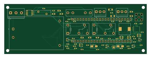
About the Bridge experiment project PCB
Bridge experiment project is an open source PCB design by Takingo, published on GitHub. It is a 4-layer board measuring 130 × 46 mm, with 75 components from 35 distinct parts.
Other key parts include the DWM3000, TXB0104RUT, SN74LVC1T45DCK, HLK-10M05 and TPS54331DR. By type, the board carries 36 capacitors, 14 resistors, 8 ICs, 4 transistors, 3 connectors and 2 relays.
From the project
OmniCircuit AI is a local proof of concept for an autonomous PCB/PCBA design and manufacturing suite. The current implementation focuses on the ESP32-S3 + DWM3000 UWB Anchor example and establishes the architecture for:
OmniCircuit AI is a local proof of concept for an autonomous PCB/PCBA design and manufacturing suite. The current implementation focuses on the ESP32-S3 + DWM3000 UWB Anchor example and establishes the architecture for:
- Parsing structured schematic, BOM, and PCB constraint inputs. - Running deterministic engineering checks for RF, isolation, power, level shifting, expansion, and testability requirements. - Producing AI design, validation, and manufacturing handoff reports. - Presenting the project state in a Flutter dashboard.
Main components on the Bridge experiment project
Bridge experiment project bill of materials (BOM)
75 components, 35 distinct parts — part numbers from the project's BOM.
| Qty | Part | Footprint | Refs |
|---|---|---|---|
| 1 | DWM3000 Decawave | DWM3000 | U2 |
| 1 | TXB0104RUT HLK-10M05 Various | Converter_ACDC_Hi-Link_HLK-10Mxx | U3 |
| 1 | SN74LVC1T45DCK TPS54331DR Various | SOIC-8_3.9x4.9mm_P1.27mm | U4 |
| 1 | SN74LVC1T45DCK TPS780180200DRV Various | SOT-23-5 | U5 |
| 1 | HLK-10M05 TXB0104RGYR HLK | WQFN-14-1EP_2.5x2.5mm_P0.5mm_EP1.45x1.45mm | U6 |
| 1 | TPS54331DR SN74LVC1T45DBVR Various | SOT-23-6 | U7 |
| 1 | SN74LVC1T45DBVR | SOT-23-6 | U13 |
| 1 | SN74LVC1T45DBVR Various | SOT-23-6 | U14 |
| 2 | 2N7002 | SOT-23 | Q1, Q2 |
| 2 | 2N7002 Various | SOT-23 | Q3, Q4 |
| 1 | AC Mains 3-pin | TerminalBlock_Phoenix_PT-1,5-3-5.0-H_1x03_P5.00mm_Horizontal | J1 |
| 2 | Vida Terminali 3-pin 3.5mm | TerminalBlock_Phoenix_PT-1,5-3-3.5-H_1x03_P3.50mm_Horizontal | J3, J4 |
| 1 | SMA Disi Edge Mount 50Ω | SMA_Amphenol_132134_Vertical | ANT1 |
| 1 | 0451.500MRL 0215001.MXP Various | Fuseholder_Littelfuse_100_series_5x20mm | F1 |
| 2 | G5Q-14-DC5 Various | Relay_SPDT_Omron-G5Q-1 | K1, K2 |
| 1 | 14D471K | RV_Disc_D15.5mm_W4.5mm_P7.5mm | RV1 |
| 2 | PinSocket_1x22_P2.54mm | PinSocket_1x22_P2.54mm_Vertical | SK1, SK2 |
| 2 | 1N5819 Various | D_SMA | D2, D3 |
| 1 | CDRH104R-220NC Various | L_10.4x10.4_H4.8 | L1 |
| 2 | 10µF/50V Elektrolitik | C_0603_1608Metric | C1, C2 |
Show 15 more
| Qty | Part | Footprint | Refs |
|---|---|---|---|
| 2 | 22µF/10V X5R 1206 | C_1206_3216Metric | C21, C22 |
| 2 | 4.7µF/50V X7R 0805 | C_0805_2012Metric | C23, C24 |
| 2 | 10µF/6.3V X5R 0805 | C_0805_2012Metric | C25, C26 |
| 10 | 100nF/16V X7R 0603 | C_0603_1608Metric | C27, C28, C29, C30, C33, C34, C35, C36 +2 |
| 4 | 100nF/50V X7R 0603 | C_0603_1608Metric | C39, C40, C41, C42 |
| 14 | 100nF | C_0603_1608Metric | C90, C91, C92, C93, C94, C95, C96, C97 +6 |
| 1 | RC0805FR-07100KL 10kΩ 0805 1% Various | R_0603_1608Metric | R14 |
| 1 | RC0805FR-07312KL 31.6kΩ 0805 1% Various | R_0603_1608Metric | R15 |
| 2 | RC0805FR-07330RL 330Ω 0805 1/4W Various | R_0805_2012Metric | R16, R17 |
| 2 | RC0805FR-0710KL 10kΩ 0805 1/4W Various | R_0805_2012Metric | R18, R19 |
| 1 | RC0603FR-0710KL 100Ω 0805 1/4W Various | R_0805_2012Metric | R20 |
| 1 | RC0603FR-0733RL 100Ω 0805 1/4W Various | R_0805_2012Metric | R21 |
| 2 | 100Ω 0805 1/4W | R_0805_2012Metric | R22, R23 |
| 2 | 100Ω 0805 1/4W | R_0603_1608Metric | R31, R32 |
| 2 | 1kΩ 0805 1/4W | R_0603_1608Metric | R41, R42 |
Bridge experiment project design files
The KiCad project lives in the Takingo/Mypcb35 repository on GitHub; these links point at the commit this page was built from.
Bridge experiment project: common questions
How big is the Bridge experiment project PCB?
The Bridge experiment project measures 130 × 46 mm, has 4 copper layers and is 1.6 mm thick.
How many components are on the Bridge experiment project?
75 components, from 35 distinct parts, with part numbers taken from the project's own BOM. The full bill of materials is listed on this page.
Where can I download the Bridge experiment project design files?
From the Takingo/Mypcb35 repository on GitHub, which has the KiCad layout and the BOM; the links under Design files point to each one.
Can I use the Bridge experiment project design in my own project?
The repository has no license, so all rights stay with Takingo. Use it as a reference, and ask the author before reusing the design.
More boards in Mypcb35
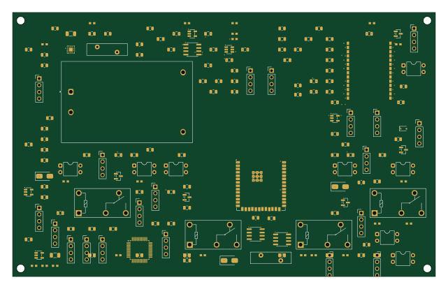 ESP32
ESP32Esp32 s3 dwm3000 uwb anchor with relay outputs
160 × 100 mm322 parts4LNo license0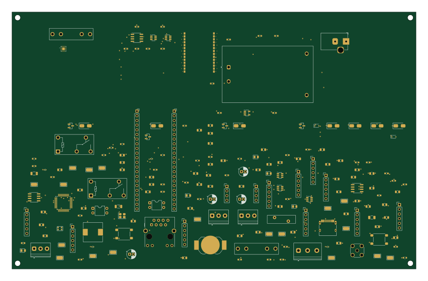
Quantum mind uwb rtls anchor v3 0 fr224 java25 test
220 × 140 mm193 parts4LNo license0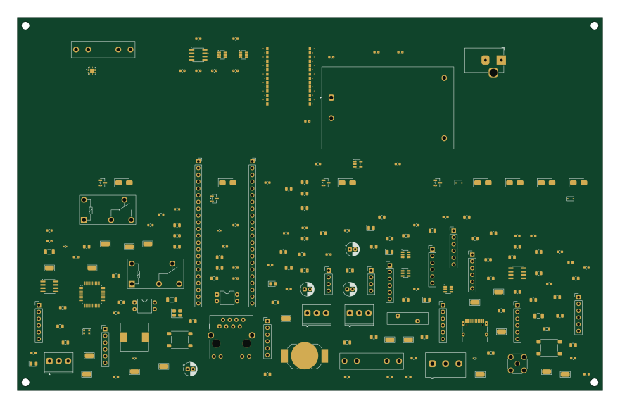
Quantum mind uwb rtls anchor v3 0 fr224 test
220 × 140 mm193 parts4LNo license0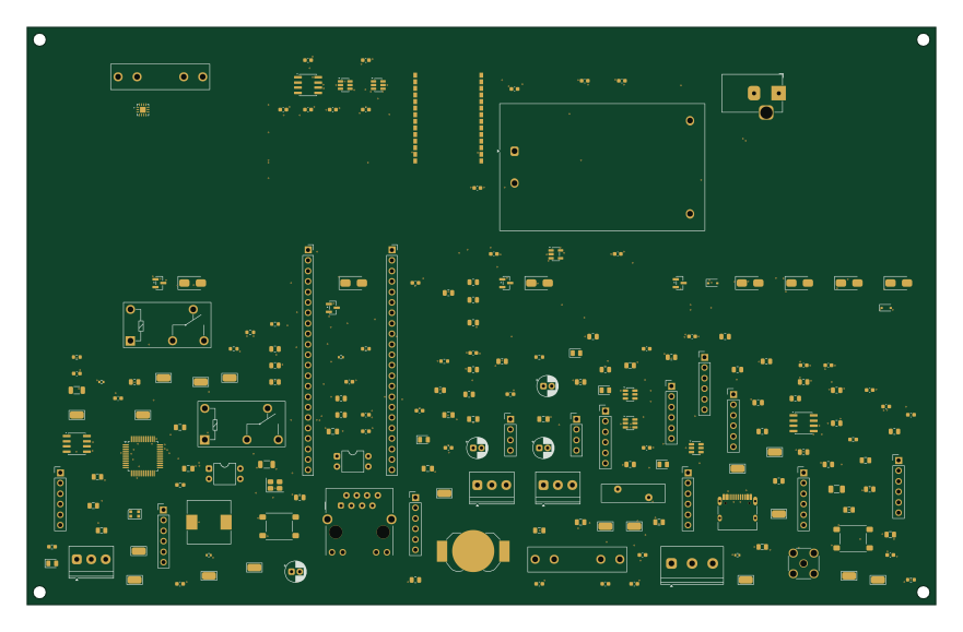
Quantum mind uwb rtls anchor v3 0
220 × 140 mm193 parts4LNo license0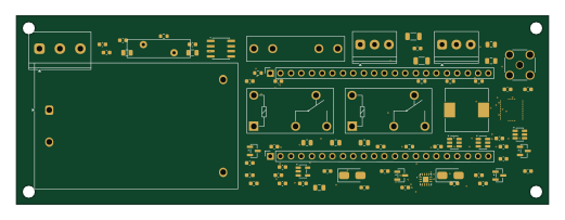
Bridge 5v project
130 × 46 mm75 parts4LNo license0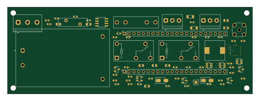
Bridge 5v project f
130 × 46 mm75 parts4LNo license0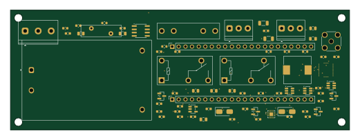
Gap bridge project
130 × 46 mm75 parts4LNo license0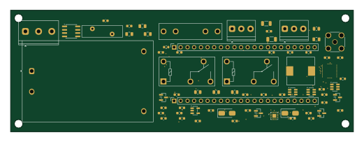
Bridge experiment project3
130 × 46 mm75 parts4LNo license0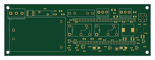
Bridge experiment project2
130 × 46 mm75 parts4LNo license0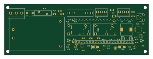
Bridge experiment
130 × 46 mm75 parts4LNo license0