
Td rgbinput

About the Td rgbinput PCB
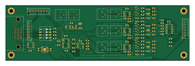
Td rgbinput is an open source PCB design by tdaede, published on GitHub. It is a 2-layer board measuring 165 × 50 mm, with 116 components from 26 distinct parts.
Other key parts include the TLC272, ADP7142ARDZ-5.0, ADA4861-3, 74HCT00 and AT24CS01-SSHM. By type, the board carries 52 resistors, 33 capacitors, 12 ICs, 6 transistors, 3 connectors and 1 jumper.
From the project
tubes
td-rgbinput is a replacement RGB analog path, providing the color controls between the RGB input and the final amplification stage on the neck board of the CRT.
Most consumer sets use an integrated RGB amplification IC, however none of these are still in production. Thus, this PCB was designed to instead use modern discrete amplifier components.
The primary challenge of the board is providing the global gain control across all 3 channels. This requires a voltage controlled amplifier, which is a difficult circuit to create when cross channel matching is desired.
Main components on the Td rgbinput
Td rgbinput bill of materials (BOM)
116 components, 26 distinct parts.
| Qty | Part | Footprint | Refs |
|---|---|---|---|
| 4 | TLC272 | SOIC-8_3.9x4.9mm_P1.27mm | U1, U12, U13, U14 |
| 1 | ADP7142ARDZ-5.0 | SOIC-8-1EP_3.9x4.9mm_P1.27mm_EP2.29x3mm | U2 |
| 1 | ADA4861-3 | SOIC-14_3.9x8.7mm_P1.27mm | U3 |
| 1 | 74HCT00 | SOIC-14_3.9x8.7mm_P1.27mm | U4 |
| 1 | AT24CS01-SSHM | SOIC-8_3.9x4.9mm_P1.27mm | U5 |
| 3 | AD8337 | LFCSP-8-1EP_3x3mm_P0.5mm_AD8337 | U6, U7, U8 |
| 1 | MAX1720EUT | SOT-23-6 | U11 |
| 6 | 2N7002NXBKR | SOT-23 | Q1, Q2, Q3, Q4, Q5, Q6 |
| 1 | Conn_01x06_Male | JST_EH_B6B-EH-A_1x06_P2.50mm_Vertical | J1 |
| 1 | Conn_01x07_Male | JST_XH_B7B-XH-AM_1x07_P2.50mm_Vertical | J2 |
| 1 | Conn_01x06_Male | JST_XH_B6B-XH-AM_1x06_P2.50mm_Vertical | J3 |
| 1 | Jumper_NC_Small | SolderJumper-2_P1.3mm_Bridged_Pad1.0x1.5mm | JP1 |
| 8 | 1k | Potentiometer_Bourns_3386P_Vertical | RV1, RV2, RV4, RV5, RV6, RV7, RV8, RV9 |
| 1 | SW_DIP_x04 | SW_DIP_SPSTx04_Slide_9.78x12.34mm_W8.61mm_P2.54mm | SW1 |
| 2 | 0.01uF | C_0805_2012Metric | C1, C2 |
| 23 | 0.1uF | C_0805_2012Metric | C3, C4, C5, C6, C7, C10, C11, C13 +15 |
| 2 | 2.2uF | C_0805_2012Metric | C8, C9 |
| 3 | 1uF | C_0805_2012Metric | C12, C16, C20 |
| 3 | 3.3uF | C_0805_2012Metric | C28, C30, C31 |
| 23 | 1k | R_0805_2012Metric | R1, R6, R17, R23, R27, R33, R34, R35 +15 |
Show 6 more
| Qty | Part | Footprint | Refs |
|---|---|---|---|
| 4 | 75 | R_0805_2012Metric | R2, R3, R4, R5 |
| 5 | 10 | R_0805_2012Metric | R7, R8, R38, R45, R52 |
| 3 | 100k | R_0805_2012Metric | R9, R20, R24 |
| 2 | 10k | R_0805_2012Metric | R11, R13 |
| 12 | 470 | R_0805_2012Metric | R12, R14, R15, R16, R19, R21, R22, R25 +4 |
| 3 | 47 | R_0805_2012Metric | R18, R31, R32 |
Td rgbinput design files
The KiCad project lives in the tdaede/td-crt repository on GitHub; these links point at the commit this page was built from.
Td rgbinput: common questions
How big is the Td rgbinput PCB?
The Td rgbinput measures 165 × 50 mm, has 2 copper layers and is 1.6 mm thick.
How many components are on the Td rgbinput?
116 components, from 26 distinct parts. The full bill of materials is listed on this page.
Where can I download the Td rgbinput design files?
From the tdaede/td-crt repository on GitHub, which has the KiCad layout and the schematic; the links under Design files point to each one.
Can I use the Td rgbinput design in my own project?
The repository has no license, so all rights stay with tdaede. Use it as a reference, and ask the author before reusing the design.
More boards in td-crt
 STM32
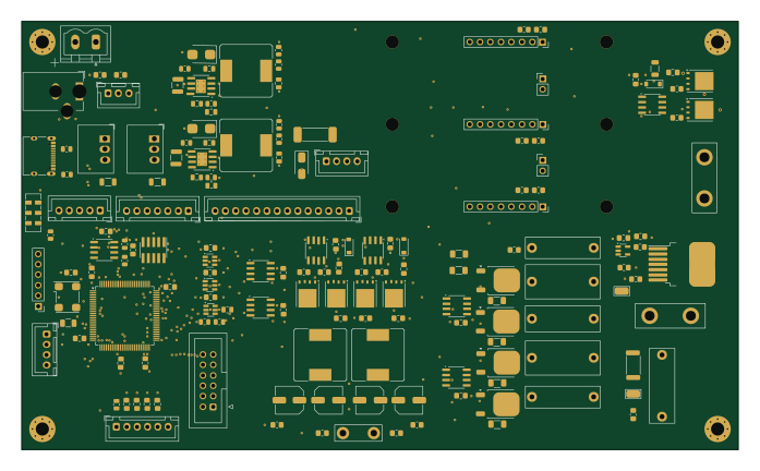
STM32Td deflect
174 × 104 mm165 parts4LNo license370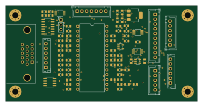
Td rgbinput lm1205
100 × 50 mm72 parts2LNo license370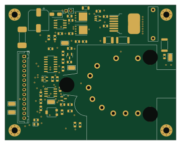
Td hv
90 × 71 mm60 parts2LNo license370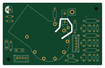
Td neck cr31
88 × 55 mm31 parts2LNo license370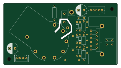
Td neck-294
103 × 55 mm28 parts2LNo license370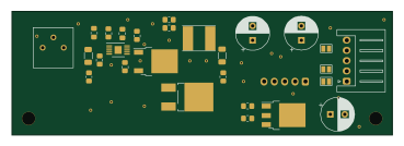
Td-180v
92 × 30 mm25 parts2LNo license370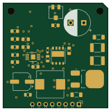
Td bplus psu gan
40 × 40 mm25 parts2LNo license370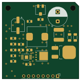
Td bplus psu
40 × 40 mm22 parts2LNo license370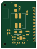
Td split rail psu
30 × 40 mm15 parts2LNo license370
Td combined remote
198 × 26 mm14 parts2LNo license370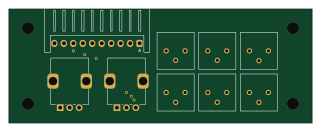
Td rgbinput remote
80 × 30 mm9 parts2LNo license370