
Td rgbinput remote

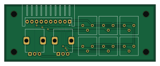
About the Td rgbinput remote PCB
Td rgbinput remote is an open source PCB design by tdaede, published on GitHub. It is a 2-layer board measuring 80 × 30 mm, with 9 components from 3 distinct parts.
It belongs with the power & battery designs in this gallery.
From the project
tubes
This repo contains work-in-progress electronics to control a CRT monitor (aka a CRT chassis).
It is divided up into several separate projects, as follows:
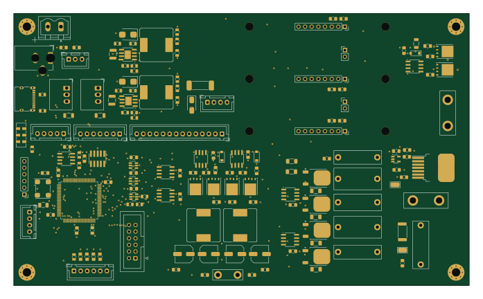
td-deflect** - Main PCB, containing microcontroller, horizontal and vertical deflection circuits, RGB amplifier, B+ power supply, 12V and -12V power supplies, and heater power supply. Functional with an enormous amount of rework.
Td rgbinput remote bill of materials (BOM)
9 components, 3 distinct parts.
| Qty | Part | Footprint | Refs |
|---|---|---|---|
| 1 | Conn_01x10_Pin | JST_XH_S10B-XH-A_1x10_P2.50mm_Horizontal | J1 |
| 2 | R_Potentiometer | Potentiometer_Alps_RK09K_Single_Vertical | RV1, RV2 |
| 6 | R_Potentiometer_Trim | Potentiometer_Bourns_3386P_Vertical | RV3, RV4, RV5, RV6, RV7, RV8 |
Td rgbinput remote design files
The KiCad project lives in the tdaede/td-crt repository on GitHub; these links point at the commit this page was built from.
Td rgbinput remote: common questions
How big is the Td rgbinput remote PCB?
The Td rgbinput remote measures 80 × 30 mm, has 2 copper layers and is 1.6 mm thick.
How many components are on the Td rgbinput remote?
9 components, from 3 distinct parts. The full bill of materials is listed on this page.
Where can I download the Td rgbinput remote design files?
From the tdaede/td-crt repository on GitHub, which has the KiCad layout and the schematic; the links under Design files point to each one.
Can I use the Td rgbinput remote design in my own project?
The repository has no license, so all rights stay with tdaede. Use it as a reference, and ask the author before reusing the design.
More boards in td-crt
 STM32
STM32Td deflect
174 × 104 mm165 parts4LNo license370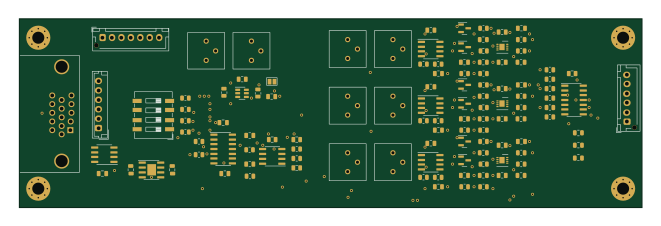
Td rgbinput
165 × 50 mm116 parts2LNo license370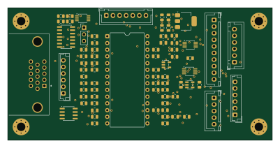
Td rgbinput lm1205
100 × 50 mm72 parts2LNo license370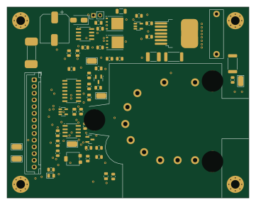
Td hv
90 × 71 mm60 parts2LNo license370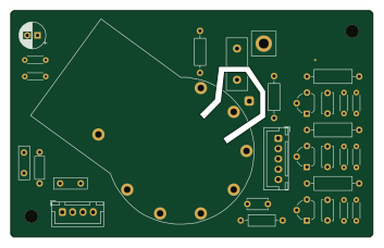
Td neck cr31
88 × 55 mm31 parts2LNo license370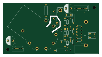
Td neck-294
103 × 55 mm28 parts2LNo license370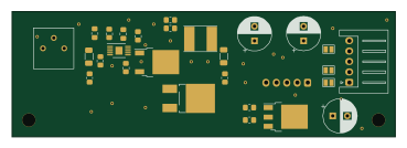
Td-180v
92 × 30 mm25 parts2LNo license370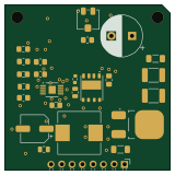
Td bplus psu gan
40 × 40 mm25 parts2LNo license370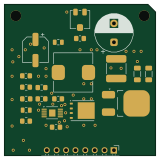
Td bplus psu
40 × 40 mm22 parts2LNo license370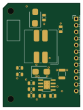
Td split rail psu
30 × 40 mm15 parts2LNo license370
Td combined remote
198 × 26 mm14 parts2LNo license370
Similar boards

Stack chan
stack-chan
50 × 50 mm33 parts2LApache-2.01.7k
Display Carrier
AxxAxx
35.6 × 58.2 mm5 parts2LGPL-3.01.7k
ControllerCurrentShuntAddOn
stuartpittaway
26 × 16.9 mm9 parts2LCC-BY-NC-4.01.1k
Module 16S PassiveBalanceAddOn
61 × 74 mm86 parts2LCC-BY-NC-4.01.1k
TemperaturePCB PANEL
116 × 75.5 mm178 parts2LCC-BY-NC-4.01.1k
ProgrammingAdapter
10.5 × 83 mm3 parts2LCC-BY-NC-4.01.1k