
Hardwareddc aux breakout

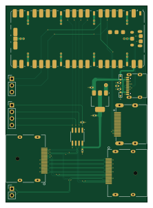
About the Hardwareddc aux breakout
Hardwareddc aux breakout is an open source RP2040/RP2350 PCB design by TeaRex-coder, published on GitHub under the BSD-3-Clause license. It is a 4-layer board measuring 54.3 × 75 mm, with 19 components from 17 distinct parts.
Its main chip is the RaspberryPi_Pico, from the RP2040/RP2350 family. Other key parts include the SN65MLVD200AD. By type, the board carries 7 connectors, 4 capacitors, 3 resistors, 2 ICs, 2 diodes and 1 module.
It belongs with the dev boards & breakouts designs in this gallery.
From the project
a custom PCB that makes adjusting monitor settings easy and convenient
I do a lot of work behind the scene to learn about DDC-related tech. In this directory, I want to share some of my fun HardwareDDC experiments.
This board uses the PTN3392 DisplayPort to VGA IC to convert DP Aux into i2c
- This solution is jank and pretty unstable - Next time, I'll try using TI's M-LVDS transceivers to interact with the Aux channel
This board attempts to "sniff" the DisplayPort auxiliary channel using TI's SN65MLVD200AD.
Main components on the Hardwareddc aux breakout
Hardwareddc aux breakout bill of materials (BOM)
19 components, 17 distinct parts — part numbers from the project's BOM.
| Qty | Part | Footprint | Refs |
|---|---|---|---|
| 1 | SN65MLVD200AD SN65MLVD200ADR | SOIC-8_3.9x4.9mm_P1.27mm | U1 |
| 1 | SN65MLVD200AD AMS1117-3.3 | SOT-223-3_TabPin2 | U2 |
| 1 | RaspberryPi_Pico | RaspberryPi_Pico_SMD | A1 |
| 1 | 47272-0001 Conn_01x04_Pin | PinHeader_1x04_P2.54mm_Vertical | J1 |
| 1 | USB_C_Receptacle | USB-C-SMD_TYPE-C-6PIN-2MD-073 | J2 |
| 1 | Conn_01x03_Pin | PinHeader_1x03_P2.54mm_Vertical | J3 |
| 1 | 47272-0001 Conn_01x02_Pin | PinHeader_1x02_P2.54mm_Vertical | J4 |
| 2 | 472720001 | CONN_47272-0001_MOL | J5, J6 |
| 1 | CONN_02X02_ODD_EVEN HDMI_A_1.4 | HDMI-SMD_HDMI-19PIN-043 | J7 |
| 1 | D_TVS | D_SOD-523 | D1 |
| 1 | D_Schottky | D_SOD-523 | D2 |
| 1 | 100N 100nF | C_0402_1005Metric | C1 |
| 1 | 100nF | C_0402_1005Metric | C2 |
| 2 | 100N 10uF | C_0402_1005Metric | C3, C4 |
| 1 | 10K 5.1K | R_0402_1005Metric | R1 |
| 1 | 3K3 5.1K | R_0402_1005Metric | R2 |
| 1 | 1K5 10K | R_0402_1005Metric | R3 |
Hardwareddc aux breakout design files
The KiCad project lives in the TeaRex-coder/hardwareddc repository on GitHub; these links point at the commit this page was built from.
Hardwareddc aux breakout: common questions
What microcontroller does the Hardwareddc aux breakout use?
The Hardwareddc aux breakout is built around the RaspberryPi_Pico, from the RP2040/RP2350 family.
How big is the Hardwareddc aux breakout?
The Hardwareddc aux breakout measures 54.3 × 75 mm, has 4 copper layers and is 1.564 mm thick.
How many components are on the Hardwareddc aux breakout?
19 components, from 17 distinct parts, with part numbers taken from the project's own BOM. The full bill of materials is listed on this page.
Where can I download the Hardwareddc aux breakout design files?
From the TeaRex-coder/hardwareddc repository on GitHub, which has the KiCad layout, the schematic and the BOM; the links under Design files point to each one.
Can I use the Hardwareddc aux breakout design in my own project?
Yes, under the terms of its BSD-3-Clause license, which TeaRex-coder chose for the repository.
Can I test firmware for the Hardwareddc aux breakout without the hardware?
Yes. HardLabs builds a simulation of the board from its netlist and BOM, so you can run and debug RP2040/RP2350 firmware against it before you order a PCB.
More boards in hardwareddc
Similar boards
 RP2040/RP2350
Open Book Abridged Edition
joeycastillo
85 × 115 mm29 parts2LCC-BY-SA-4.08.1k RP2040/RP2350
Corne
foostan
277.2 × 107.5 mm164 parts2LCC-BY-4.07.7k RP2040/RP2350
Corne
277.2 × 107.5 mm164 parts2LCC-BY-4.07.7k RP2040/RP2350
LogicAnalyzer
gusmanb
57 × 55.2 mm6 parts2LGPL-3.05.0k RP2040/RP2350
Jitx design
55.5 × 65 mm26 parts4LGPL-3.05.0k RP2040/RP2350
Main
google
98 × 71 mm102 parts2LApache-2.02.9k