
Cardradio

About the Cardradio PCB
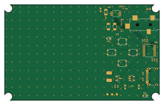
Cardradio is an open source RISC-V PCB design by tend876, published on GitHub. It is a 2-layer board measuring 83.2 × 51.6 mm, with 42 components from 29 distinct parts.
Its main chip is the WCH CH32V003F4P6 (TSSOP-20), from the RISC-V family. Other key parts include the RDA5807M (MSOP-10), Torex XC6206P302MR (3.0 V LDO) and MCP73831T-2ACI/OT. By type, the board carries 12 resistors, 11 capacitors, 4 ICs, 4 switches, 4 inductors and 3 connectors.
It belongs with the rf & radio and power & battery designs in this gallery.
From the project
The 1986 Casio RD-10 was an 86 × 54 × 2.2 mm card with a Philips TDA7020T, a CR2016 cell and a proprietary flat earphone plug. The earphone lead was also the antenna and the power switch. CR-1 keeps that behaviour but uses modern parts:
The 1986 Casio RD-10 was an 86 × 54 × 2.2 mm card with a Philips TDA7020T, a CR2016 cell and a proprietary flat earphone plug. The earphone lead was also the antenna and the power switch. CR-1 keeps that behaviour but uses modern parts:
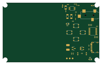
PCB: 2 layers, 0.4 mm, 83.2 × 51.6 mm with notches for the four screw bosses. All components are on the top side and the LiPo is taped on top of the board. JLCPCB-class rules: 0.15/0.15 mm track/space, 0.3/0.6 mm vias, GND pours on both layers, about 220 stitching vias.
Main components on the Cardradio
Cardradio bill of materials (BOM)
42 components, 29 distinct parts — part numbers from the project's BOM.
| Qty | Part | Footprint | Refs |
|---|---|---|---|
| 1 | RDA5807M (MSOP-10) RDA5807M | MSOP-10_3x3mm_P0.5mm | U1 |
| 1 | WCH CH32V003F4P6 (TSSOP-20) CH32V003F4P6 | TSSOP-20_4.4x6.5mm_P0.65mm | U2 |
| 1 | Torex XC6206P302MR (3.0 V LDO) XC6206P302MR | SOT-23 | U3 |
| 1 | MCP73831T-2ACI/OT MCP73831-2 | SOT-23-5 | U4 |
| 1 | 32.768 kHz 3215, 12.5 pF 32.768kHz | Crystal_SMD_3215-2Pin_3.2x1.5mm | Y1 |
| 1 | CUI/Same Sky SJ-3524-SMT-TR SJ-3524-SMT | Jack_3.5mm_CUI_SJ-3524-SMT_Horizontal | J1 |
| 1 | HRO TYPE-C-31-M-12 USB-C | USB_C_Receptacle_HRO_TYPE-C-31-M-12 | J2 |
| 1 | (pads, pogo / WCH-LinkE) SWIO | ProgPads_1x03_P2.54mm | J3 |
| 1 | LP303450 3.7 V ~450 mAh w/ PCM (3.0x34x50 mm) LiPo 3.7V | LiPo_Pads_2x | BT1 |
| 1 | C&K PTS810 SJM 250 SMTR LFS VOL+ | SW_SPST_PTS810 | SW1 |
| 1 | C&K PTS810 SJM 250 SMTR LFS VOL- | SW_SPST_PTS810 | SW2 |
| 1 | C&K PTS810 SJM 250 SMTR LFS SEEK< | SW_SPST_PTS810 | SW3 |
| 1 | C&K PTS810 SJM 250 SMTR LFS SEEK> | SW_SPST_PTS810 | SW4 |
| 1 | 0603 red LED RED | LED_0603_1608Metric | D1 |
| 1 | 0603 green LED GREEN | LED_0603_1608Metric | D2 |
| 2 | BLM15HD182SN1D 1k8@100MHz | L_0402_1005Metric | FB1, FB2 |
| 1 | BLM18HE152SN1D 1k5@100MHz | L_0603_1608Metric | FB3 |
| 1 | 0402 100nH (e.g. LQG15HS R10) 100nH | L_0402_1005Metric | L1 |
| 2 | 0603 4.7uF 10V X5R 4.7uF | C_0603_1608Metric | C1, C2 |
| 2 | 0402 1uF 10V X5R 1uF | C_0402_1005Metric | C3, C4 |
Show 9 more
| Qty | Part | Footprint | Refs |
|---|---|---|---|
| 3 | 0402 100nF X7R 100nF | C_0402_1005Metric | C5, C6, C7 |
| 1 | 0603 10uF 10V X5R 10uF | C_0603_1608Metric | C8 |
| 2 | 1206 100uF 6.3V X5R (e.g. CL31A107MQHNNNE) 100uF | C_1206_3216Metric | C10, C11 |
| 1 | 0402 22pF C0G 22pF | C_0402_1005Metric | C12 |
| 2 | 0402 1k 1% 1k | R_0402_1005Metric | R1, R11 |
| 2 | 0402 5k1 1% 5k1 | R_0402_1005Metric | R2, R3 |
| 4 | 0402 4k7 1% 4k7 | R_0402_1005Metric | R4, R7, R8, R10 |
| 3 | 0402 1M 1% 1M | R_0402_1005Metric | R5, R6, R9 |
| 1 | 0402 10k 1% 10k | R_0402_1005Metric | R12 |
Cardradio design files
The KiCad project lives in the tend876/Card-Radio-1 repository on GitHub; these links point at the commit this page was built from.
- Layoutkicad/cardradio.kicad_pcb
- Schematickicad/cardradio.kicad_sch
- BOMfab/cardradio-bom.csv
Cardradio: common questions
What microcontroller does the Cardradio use?
The Cardradio is built around the WCH CH32V003F4P6 (TSSOP-20), from the RISC-V family.
How big is the Cardradio PCB?
The Cardradio measures 83.2 × 51.6 mm, has 2 copper layers and is 0.4 mm thick.
How many components are on the Cardradio?
42 components, from 29 distinct parts, with part numbers taken from the project's own BOM. The full bill of materials is listed on this page.
Where can I download the Cardradio design files?
From the tend876/Card-Radio-1 repository on GitHub, which has the KiCad layout, the schematic and the BOM; the links under Design files point to each one.
Can I use the Cardradio design in my own project?
The repository has no license, so all rights stay with tend876. Use it as a reference, and ask the author before reusing the design.
Can I test firmware for the Cardradio without the hardware?
Yes. HardLabs builds a simulation of the board from its netlist and BOM, so you can run and debug RISC-V firmware against it before you order a PCB.
More boards in Card-Radio-1
Similar boards
 RISC-V
Audio
byrantech
27.8 × 22.3 mm38 parts2LMIT4.3k RISC-V
Keybit
notaroomba
19.1 × 19.1 mm19 parts2LNo license438 RISC-V
Workbench-1 Controller
Quchaosheng
160 × 130 mm106 parts8LApache-2.0212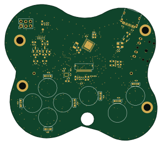 RISC-V
Froggyswadge
cnlohr
81.5 × 72.2 mm92 parts2LMIT105 RISC-V
Keytartouch
152.5 × 117.5 mm69 parts2LMIT105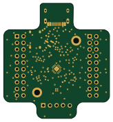 RISC-V
Ch32v003f4u6 with wsled
40.6 × 44.5 mm26 parts2LMIT105