
RF-UPS-Monitor

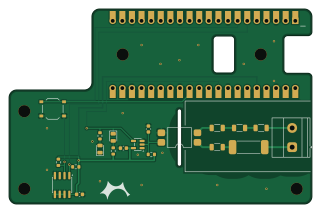
About the RF-UPS-Monitor PCB
RF-UPS-Monitor is an open source RP2040/RP2350 PCB design by TheKingOfChaos, published on GitHub. It is a 2-layer board measuring 80 × 51.5 mm, with 21 components from 16 distinct parts.
Its main chip is the W5500-EVB-Pico-PoE, from the RP2040/RP2350 family. Other key parts include the LTV-814S-TA1, SN74LVC1G14DBVR and TMP1075DR. By type, the board carries 9 resistors, 4 ICs, 3 capacitors, 2 diodes, 1 connector and 1 fuse.
It belongs with the power & battery, sensors and dev boards & breakouts designs in this gallery.
From the project
A 2-layer carrier board for the WIZnet W5500-EVB-Pico-PoE. It is 80 x 51.5 mm: exactly as long as the module, so both short edges line up with the module. The board extends 1.5 mm above the module for the solder fillets. It has 5x M3 holes, with centres at (4, 25.5), (4, 46) and
A 2-layer carrier board for the WIZnet W5500-EVB-Pico-PoE. It is 80 x 51.5 mm: exactly as long as the module, so both short edges line up with the module. The board extends 1.5 mm above the module for the solder fillets. It has 5x M3 holes, with centres at (4, 25.5), (4, 46) and (76, 46) mm from the module's top-left corner, plus H4 (30, 10.5) and H5 (66.5, 10.5) under the module, between the header rows. All SMD parts are on the top side. The only through-hole parts are the module headers and the screw terminal.
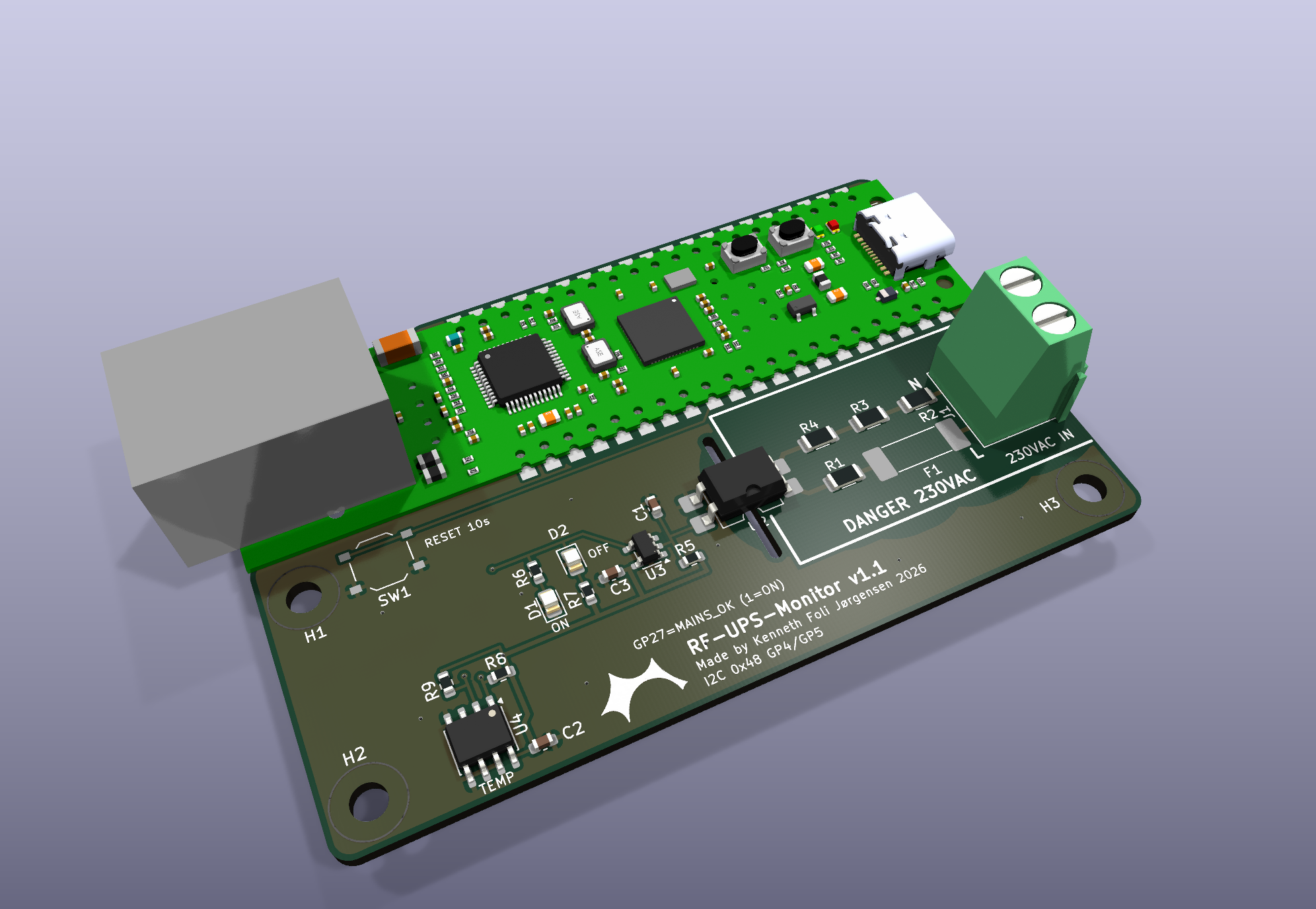
Main components on the RF-UPS-Monitor
RF-UPS-Monitor bill of materials (BOM)
21 components, 16 distinct parts — part numbers from the project's BOM.
| Qty | Part | Footprint | Refs |
|---|---|---|---|
| 1 | W5500-EVB-Pico-PoE | W5500-EVB-Pico-PoE_Socket | U1 |
| 1 | LTV-814S-TA1 LTV-814S | SMDIP-4_W9.53mm | U2 |
| 1 | SN74LVC1G14DBVR | SOT-23-5 | U3 |
| 1 | TMP1075DR | SOIC-8_3.9x4.9mm_P1.27mm | U4 |
| 1 | Phoenix 1715721 (MKDS 1,5/2-5,08) 230VAC L/N | TerminalBlock_Phoenix_MKDS-1,5-2-5.08_1x02_P5.08mm_Horizontal | J1 |
| 1 | Schurter 3403.0156.11 (UMT 250, T 100 mA, 250 VAC) T100mA 250VAC | Fuse_Schurter_UMT250 | F1 |
| 1 | XKB TS-1187A-B-A-B FACTORY RESET | SW_Push_1P1T_XKB_TS-1187A | SW1 |
| 1 | C2297 Green | LED_0805_2012Metric | D1 |
| 1 | C84256 Red | LED_0805_2012Metric | D2 |
| 1 | 1UF 1uF | C_0603_1608Metric | C1 |
| 2 | 100NF 100nF | C_0603_1608Metric | C2, C3 |
| 4 | C2889820 68k 1206 200V | R_1206_3216Metric | R1, R2, R3, R4 |
| 1 | 47K 47k | R_0603_1608Metric | R5 |
| 1 | 100R | R_0603_1608Metric | R6 |
| 1 | 330R | R_0603_1608Metric | R7 |
| 2 | 4.7K 4.7k | R_0603_1608Metric | R8, R9 |
RF-UPS-Monitor design files
The KiCad project lives in the TheKingOfChaos/RF-UPS-Monitor repository on GitHub; these links point at the commit this page was built from.
RF-UPS-Monitor: common questions
What microcontroller does the RF-UPS-Monitor use?
The RF-UPS-Monitor is built around the W5500-EVB-Pico-PoE, from the RP2040/RP2350 family.
How big is the RF-UPS-Monitor PCB?
The RF-UPS-Monitor measures 80 × 51.5 mm, has 2 copper layers and is 1.6 mm thick.
How many components are on the RF-UPS-Monitor?
21 components, from 16 distinct parts, with part numbers taken from the project's own BOM. The full bill of materials is listed on this page.
Where can I download the RF-UPS-Monitor design files?
From the TheKingOfChaos/RF-UPS-Monitor repository on GitHub, which has the KiCad layout, the schematic and the BOM; the links under Design files point to each one.
Can I use the RF-UPS-Monitor design in my own project?
The repository has no license, so all rights stay with TheKingOfChaos. Use it as a reference, and ask the author before reusing the design.
Can I test firmware for the RF-UPS-Monitor without the hardware?
Yes. HardLabs builds a simulation of the board from its netlist and BOM, so you can run and debug RP2040/RP2350 firmware against it before you order a PCB.
Similar boards
 RP2040/RP2350
OSO-BOOK-C1
joeycastillo
85 × 115 mm29 parts2LCC-BY-SA-4.08.1k RP2040/RP2350
Corne cherry
foostan
277.2 × 107.5 mm164 parts2LCC-BY-4.07.7k RP2040/RP2350
Corne chocolate
277.2 × 107.5 mm164 parts2LCC-BY-4.07.7k RP2040/RP2350
Jitx design
gusmanb
55.5 × 65 mm26 parts4LGPL-3.05.0k RP2040/RP2350
LogicAnalyzer
57 × 55.2 mm6 parts2LGPL-3.05.0k RP2040/RP2350
Main
google
98 × 71 mm102 parts2LApache-2.02.9k