
Robopad

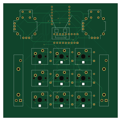
About the Robopad PCB
Robopad is an open source RP2040/RP2350 PCB design by TheScientist101, published on GitHub. It is a 2-layer board measuring 100 × 100 mm, with 34 components from 10 distinct parts.
Its main chip is the XIAO-RP2040-DIP, from the RP2040/RP2350 family. Other key parts include the RS30111AC00V, Left Joystick, Right Joystick, MCP23008-xP and MCP3426Axx-xSN. By type, the board carries 9 switches, 9 LEDs, 9 diodes and 7 ICs.
It belongs with the keyboards and robotics & motion designs in this gallery.
From the project
A macropad to use as a controller when simulating your robot for FRC.
The Robopad was designed because no controllers are mapped correctly for robot simulation. The main features I needed were the two joysticks but I decided to add some sliders to allow me to control the brightness of my screen and some keyswitches to allow me to have more inputs when I need them. Along with the keyswitches, I added some LEDs which will (hopefully) make the macropad look cooler.
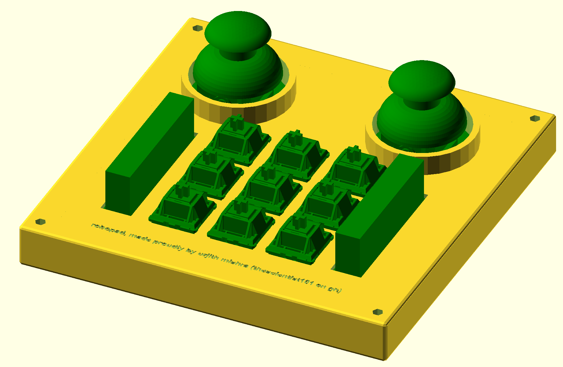
Main components on the Robopad
Robopad bill of materials (BOM)
34 components, 10 distinct parts.
| Qty | Part | Footprint | Refs |
|---|---|---|---|
| 1 | RS30111AC00V Left Slider | RS30111AC00V | IC1 |
| 1 | RS30111AC00V Right Slider | RS30111AC00V | IC2 |
| 1 | XIAO-RP2040-DIP | XIAO-SAMD21-DIP | U1 |
| 1 | Left Joystick | XDCR_COM-09032 | U2 |
| 1 | Right Joystick | XDCR_COM-09032 | U3 |
| 1 | MCP23008-xP | DIP-18_W7.62mm | U4 |
| 1 | MCP3426Axx-xSN | SOIC-8_3.9x4.9mm_P1.27mm | U5 |
| 9 | SW_Push | SW_Cherry_MX_PCB_1.00u | SW1, SW2, SW3, SW4, SW5, SW6, SW7, SW8 +1 |
| 9 | MX_SK6812MINI-E | LED_MX_6028R | LED1, LED2, LED3, LED4, LED5, LED6, LED7, LED8 +1 |
| 9 | 1N4148 | D_DO-35_SOD27_P7.62mm_Horizontal | D1, D2, D3, D4, D5, D6, D7, D8 +1 |
Robopad design files
The KiCad project lives in the TheScientist101/robopad repository on GitHub; these links point at the commit this page was built from.
- Layoutpcb/robopad.kicad_pcb
- Schematicpcb/robopad.kicad_sch
Robopad: common questions
What microcontroller does the Robopad use?
The Robopad is built around the XIAO-RP2040-DIP, from the RP2040/RP2350 family.
How big is the Robopad PCB?
The Robopad measures 100 × 100 mm, has 2 copper layers and is 1.6 mm thick.
How many components are on the Robopad?
34 components, from 10 distinct parts. The full bill of materials is listed on this page.
Where can I download the Robopad design files?
From the TheScientist101/robopad repository on GitHub, which has the KiCad layout and the schematic; the links under Design files point to each one.
Can I use the Robopad design in my own project?
The repository has no license, so all rights stay with TheScientist101. Use it as a reference, and ask the author before reusing the design.
Can I test firmware for the Robopad without the hardware?
Yes. HardLabs builds a simulation of the board from its netlist and BOM, so you can run and debug RP2040/RP2350 firmware against it before you order a PCB.
Similar boards
 RP2040/RP2350
OSO-BOOK-C1
joeycastillo
85 × 115 mm29 parts2LCC-BY-SA-4.08.1k RP2040/RP2350
Corne chocolate
foostan
277.2 × 107.5 mm164 parts2LCC-BY-4.07.7k RP2040/RP2350
Corne cherry
277.2 × 107.5 mm164 parts2LCC-BY-4.07.7k RP2040/RP2350
Jitx design
gusmanb
55.5 × 65 mm26 parts4LGPL-3.05.0k RP2040/RP2350
LogicAnalyzer
57 × 55.2 mm6 parts2LGPL-3.05.0k RP2040/RP2350
Main
google
98 × 71 mm102 parts2LApache-2.02.9k