
TFI2CADT01

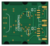
About the TFI2CADT01 PCB
TFI2CADT01 is an open source PCB design by ThunderFly-aerospace, published on GitHub under the GPL-3.0 license. It is a 2-layer board measuring 25 × 23 mm, with 29 components from 13 distinct parts.
Other key parts include the MIC5504-3.3YM5 and LTC4317. By type, the board carries 15 resistors, 6 connectors, 4 capacitors, 2 ICs and 2 diodes.
It belongs with the sensors designs in this gallery.
From the project
I2C address translator module, allows connection of multiple I2C devices with the same address to one bus.
TFI2CADT01 is an I2C device address changer. This function allows you to connect multiple I2C devices with the same address to one master device on the same bus.
That is a common problem in case multiple I2C sensors with the same address (or a limited number of addresses) need to be connected to one I2C master. The purpose of this module is to change the address with which the I2C master calls to the address of the target I2C (slave) device. The module is based on LTC4317 I2C address translator IC. The module is designed and optimized for use on Pixhawk-compatible drones, especially UAVs.…
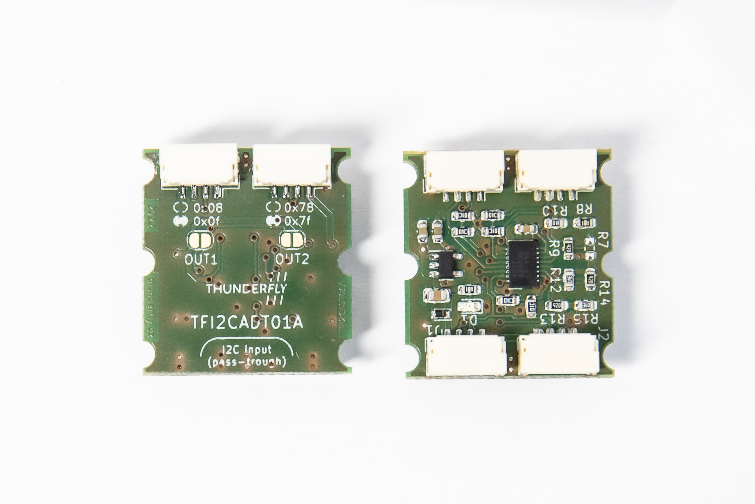
Main components on the TFI2CADT01
TFI2CADT01 bill of materials (BOM)
29 components, 13 distinct parts — part numbers from the project's BOM.
| Qty | Part | Footprint | Refs |
|---|---|---|---|
| 1 | MIC5504-3.3YM5 | SOT-23-5 | U1 |
| 1 | LTC4317 | DFN-16-1EP_3x5mm_P0.5mm_EP1.66x4.4mm | U2 |
| 6 | SM04B-GHS-TB | JST_GH_SM04B-GHS-TB_1x04-1MP_P1.25mm_Horizontal | J1, J2, J3, J4, J5, J6 |
| 1 | LED GREEN | LED_0603_1608Metric | D1 |
| 1 | BZX585-B5V6.115 | D_SOD-523 | D2 |
| 1 | 10UF 10uF | C_0805_2012Metric | C1 |
| 2 | 100NF 100nF | C_0603_1608Metric | C2, C4 |
| 1 | 1UF 1uF | C_0603_1608Metric | C3 |
| 2 | 180R | R_0603_1608Metric | R1, R8 |
| 6 | 10K 10k | R_0603_1608Metric | R2, R3, R5, R6, R16, R17 |
| 1 | - | R_0603_1608Metric | R7 |
| 3 | 887K 887k | R_0603_1608Metric | R9, R13, R14 |
| 3 | 1M | R_0603_1608Metric | R10, R12, R15 |
TFI2CADT01 design files
The KiCad project lives in the ThunderFly-aerospace/TFI2CADT01 repository on GitHub; these links point at the commit this page was built from.
TFI2CADT01: common questions
How big is the TFI2CADT01 PCB?
The TFI2CADT01 measures 25 × 23 mm, has 2 copper layers and is 1.6 mm thick.
How many components are on the TFI2CADT01?
29 components, from 13 distinct parts, with part numbers taken from the project's own BOM. The full bill of materials is listed on this page.
Where can I download the TFI2CADT01 design files?
From the ThunderFly-aerospace/TFI2CADT01 repository on GitHub, which has the KiCad layout, the schematic and the BOM; the links under Design files point to each one.
Can I use the TFI2CADT01 design in my own project?
Yes, under the terms of its GPL-3.0 license, which ThunderFly-aerospace chose for the repository.
Similar boards
Sensor smd
scottbez1
40 × 20 mm5 parts2LApache-2.04.2k
Sensors
StuckAtPrototype
15.2 × 9 mm14 parts4LApache-2.03.8k
Microphone
Mentra-Community
5.5 × 6.1 mm6 parts2LMIT1.2k
TemperaturePCB PANEL
stuartpittaway
116 × 75.5 mm178 parts2LCC-BY-NC-4.01.1k
Pots
shanteacontrols
390 × 93 mm75 parts2LApache-2.0956
USB
52 × 12.6 mm6 parts2LApache-2.0956