
Robo con for-Wi-Fi

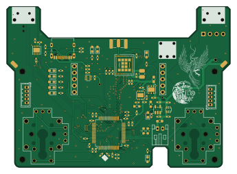
About the Robo con for-Wi-Fi PCB
Robo con for-Wi-Fi is an open source STM32 PCB design by tmcit-ararobo-2026a, published on GitHub under the MIT license. It is a 4-layer board measuring 86 × 62 mm, with 101 components from 41 distinct parts.
Its main chip is the STM32H7A3RGTX, from the STM32 family. Other key parts include the LBEE5HY2FY, FT234XD, MCP1727-1802XMF, RKJXV122400R and LD39200PU33R. By type, the board carries 37 capacitors, 25 resistors, 11 ICs, 10 diodes, 9 connectors and 6 switches.
It belongs with the iot & wireless designs in this gallery, and the repository also holds 1 earlier revision of it.
From the project
the code and pcb in this repository is wireless robot's controller.
the code and pcb in this repository is wireless robot's controller.
1. 概要 2. ドキュメント 3. コントリビューション 4. ビルド・使い方 5. システム構成 6. ライセンス
ロボコンなどの会場のなかでは2.4GHzもしくは5GHzといった周波数帯は多くの場合かなり混雑していることが多い。 こういった大会で無線による有利は勝敗に大きく作用するため、使用する周波数はできるだけ混雑していないことが望ましい。 そのため、6GHzを使うコントローラーを作成する。
Main components on the Robo con for-Wi-Fi
Robo con for-Wi-Fi bill of materials (BOM)
101 components, 41 distinct parts — part numbers from the project's BOM.
| Qty | Part | Footprint | Refs |
|---|---|---|---|
| 1 | LBEE5HY2FY | LBEE5HY2FY | U2 |
| 1 | FT234XD | WDFN-12-1EP_3x3mm_P0.45mm_EP1.7x2.5mm | U3 |
| 1 | MCP1727-1802XMF MCP1727-1802xMF | DFN-8-1EP_3x3mm_P0.65mm_EP1.55x2.4mm | U4 |
| 2 | RKJXV122400R | RKJXV122400R | U5, U7 |
| 1 | LD39200PU33R | DFN-6-1EP_3x3mm_P0.95mm_EP1.7x2.6mm | U6 |
| 1 | STM32H7A3RGTX STM32H7A3RGTx | LQFP-64_10x10mm_P0.5mm | U8 |
| 1 | MCP73831-2-OT | SOT-23-5 | U10 |
| 2 | LM66100DCK | SOT-363_SC-70-6 | U11, U15 |
| 1 | USB_Type-C | USB_C_Receptacle_Nelton_5077CR-16-SMC2-BK-TR | U18 |
| 1 | XRCGB25M000FFS1AR0 | XRCGB25M000FFS1AR0 | Y2 |
| 1 | CONN_01X04 Conn_01x04 | PinSocket_1x04_P2.54mm_Vertical | J1 |
| 1 | SMA-J | SMA_Conn | J2 |
| 2 | CONN_01X05 Conn_01x05 | JST_ZH_B5B-ZR_1x05_P1.50mm_Vertical | J3, J11 |
| 4 | CONN_01X01 Conn_01x01 | SolderWirePad_1x01_SMD_1.5x3mm | J4, J6, J8, J9 |
| 1 | CONN_01X02 Conn_01x02 | JST_PH_S2B-PH-K_1x02_P2.00mm_Horizontal | J5 |
| 1 | FHC16322ADTP | L_0603_1608Metric_Pad1.05x0.95mm_HandSolder | F1 |
| 1 | SW_Push | switch_TVAF06-A020B-R | SW1 |
| 2 | SW_Push | SKHHLPA010 | SW3, SW4 |
| 1 | SW_Push_SPDT | 4MS1R202M6QES | SW5 |
| 2 | SW_Push_SPDT | 8MS8P1B05VS2QES-C13 | SW6, SW7 |
Show 21 more
| Qty | Part | Footprint | Refs |
|---|---|---|---|
| 1 | R | D_0603_1608Metric_Pad1.05x0.95mm_HandSolder | D1 |
| 2 | G | D_0603_1608Metric_Pad1.05x0.95mm_HandSolder | D3, D16 |
| 1 | B | D_0603_1608Metric_Pad1.05x0.95mm_HandSolder | D5 |
| 4 | O | D_0603_1608Metric_Pad1.05x0.95mm_HandSolder | D10, D13, D14, D17 |
| 2 | W | D_0603_1608Metric_Pad1.05x0.95mm_HandSolder | D11, D12 |
| 1 | 2.2U 2.2u | L_1008_2520Metric_Pad1.43x2.20mm_HandSolder | L1 |
| 18 | 0.1U 0.1u | C_0402_1005Metric_Pad0.74x0.62mm_HandSolder | C12, C13, C14, C15, C16, C17, C18, C19 +10 |
| 2 | 2.2U 2.2u | C_0402_1005Metric_Pad0.74x0.62mm_HandSolder | C30, C31 |
| 2 | 18PF 18pF | C_0402_1005Metric_Pad0.74x0.62mm_HandSolder | C34, C35 |
| 3 | 1u | C_0402_1005Metric_Pad0.74x0.62mm_HandSolder | C61, C71, C80 |
| 10 | 4.7U 4.7u | C_0402_1005Metric_Pad0.74x0.62mm_HandSolder | C62, C63, C64, C74, C75, C76, C77, C79 +2 |
| 1 | 1n | C_0402_1005Metric_Pad0.74x0.62mm_HandSolder | C65 |
| 1 | 10U 10u | C_0603_1608Metric_Pad1.08x0.95mm_HandSolder | C82 |
| 15 | 1k | R_0402_1005Metric_Pad0.72x0.64mm_HandSolder | R2, R4, R6, R11, R21, R25, R32, R33 +7 |
| 2 | 22 | R_0402_1005Metric_Pad0.72x0.64mm_HandSolder | R3, R5 |
| 1 | 10K 10k | R_0402_1005Metric_Pad0.72x0.64mm_HandSolder | R23 |
| 1 | 2.2K 2.2k | R_0603_1608Metric_Pad0.98x0.95mm_HandSolder | R24 |
| 2 | 1k | R_0603_1608Metric_Pad0.98x0.95mm_HandSolder | R26, R27 |
| 2 | 4.7K 4.7k | R_0402_1005Metric_Pad0.72x0.64mm_HandSolder | R39, R40 |
| 1 | 100K 100k | R_0603_1608Metric_Pad0.98x0.95mm_HandSolder | R41 |
| 1 | WA04X102 | WA04X102 | R44 |
Robo con for-Wi-Fi design files
The KiCad project lives in the tmcit-ararobo-2026a/robo-con-for-Wi-Fi repository on GitHub; these links point at the commit this page was built from.
Robo con for-Wi-Fi: common questions
What microcontroller does the Robo con for-Wi-Fi use?
The Robo con for-Wi-Fi is built around the STM32H7A3RGTX, from the STM32 family.
How big is the Robo con for-Wi-Fi PCB?
The Robo con for-Wi-Fi measures 86 × 62 mm, has 4 copper layers and is 1.6 mm thick.
How many components are on the Robo con for-Wi-Fi?
101 components, from 41 distinct parts, with part numbers taken from the project's own BOM. The full bill of materials is listed on this page.
Where can I download the Robo con for-Wi-Fi design files?
From the tmcit-ararobo-2026a/robo-con-for-Wi-Fi repository on GitHub, which has the KiCad layout, the schematic and the BOM; the links under Design files point to each one.
Can I use the Robo con for-Wi-Fi design in my own project?
Yes, under the terms of its MIT license, which tmcit-ararobo-2026a chose for the repository.
Can I test firmware for the Robo con for-Wi-Fi without the hardware?
Yes. HardLabs builds a simulation of the board from its netlist and BOM, so you can run and debug STM32 firmware against it before you order a PCB.
Earlier revisions in the repo: robo-con-Wi-Fi
Similar boards
 STM32
LumenPnP Motherboard
opulo-inc
149 × 95 mm296 parts4LCC-BY-SA-4.03.7k STM32
Type g
google
169 × 30 mm24 parts2LApache-2.02.9k STM32
Base
52.3 × 52.3 mm36 parts2LApache-2.02.9k STM32
Main panel
234 × 84 mm26 parts4LApache-2.02.9k STM32
Type a
150 × 30 mm14 parts2LApache-2.02.9k STM32
Type c
188 × 30 mm17 parts2LApache-2.02.9k