
IMU-controller

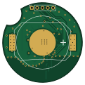
About the IMU-controller PCB
IMU-controller is an open source Nordic nRF PCB design by TomasD-git, published on GitHub under the EPL-2.0 license. It is a 4-layer board measuring 30 × 30 mm, with 29 components from 21 distinct parts.
Its main chip is the NRF52810-QFAA-R, from the Nordic nRF family. Other key parts include the FC31M2-32.768-N09LLDT, BMI270, LS L29K-G1J2-1-Z and PTS526SMG15SMTR21 LFS. By type, the board carries 16 capacitors, 5 ICs, 4 inductors, 1 crystal, 1 connector and 1 battery holder.
It belongs with the iot & wireless, power & battery and sensors designs in this gallery.
From the project
Ultra low power IMU controllers, can control anything over bluetooth using IMU, all running on coin cell battery
0. Connect device to PC using segger j-link 1. Open VS Code 2. Select connected device in left bottom corner:
1. Print all parts and assemble PCB 2. Flash 3. Place the Coin Cell battery into the holder 4. Place the PCB inside the case 5. Screw the bottom lid into the top one 6. Verify it works by clicking the button
Main components on the IMU-controller
IMU-controller bill of materials (BOM)
29 components, 21 distinct parts — part numbers from the project's BOM.
| Qty | Part | Footprint | Refs |
|---|---|---|---|
| 1 | NRF52810-QFAA-R NORDIC | UQFN-48_L6.0-W6.0-P0.40-BL-EP4.6 | U1 |
| 1 | FC31M2-32.768-N09LLDT HCI(杭晶) | CRYSTAL-SMD_L3.2-W1.5 | U2 |
| 1 | BMI270 Bosch(博世) | LGA-14_L3.0-W2.5-P0.50-BR | U3 |
| 1 | LS L29K-G1J2-1-Z OSRAM(欧司朗) | LED-SMD_L1.3-W0.8-LS1.7-FD | U4 |
| 1 | PTS526SMG15SMTR21 LFS C&K | SW-SMD_4P-L4.8-W4.8-P3.70-LS6.4-1 | U6 |
| 1 | S3232000081040 JGHC(晶光华) | CRYSTAL-SMD_4P-L3.2-W2.5-BL | X1 |
| 1 | Conn_01x05 | PinSocket_1x05_P2.00mm_Vertical | J1 |
| 1 | MY-2032-12 MYOUNG(美阳) | BAT-SMD_MY-2032-12 | BT1 |
| 1 | 3.9nH | L_0402_1005Metric | L2 |
| 1 | AN3216-245 Rainsun(霖昱微) | ANT-SMD_L3.2-W1.6-A | L3 |
| 1 | 2.7nH | L_0402_1005Metric | L4 |
| 1 | 3.3nH | L_0402_1005Metric | L5 |
| 5 | 100nF | C_0402_1005Metric | C1, C3, C4, C12, C13 |
| 1 | 4.7uF | C_0603_1608Metric | C2 |
| 1 | 100pF | C_0402_1005Metric | C5 |
| 5 | 12pF | C_0402_1005Metric | C6, C8, C9, C10, C11 |
| 1 | 1uF | C_0603_1608Metric | C7 |
| 1 | 10uF | C_0805_2012Metric | C14 |
| 1 | 0.8pF | C_0402_1005Metric | C19 |
| 1 | 1.2pF | C_0402_1005Metric | C20 |
Show 1 more
| Qty | Part | Footprint | Refs |
|---|---|---|---|
| 1 | 620 | R_0603_1608Metric | R1 |
IMU-controller design files
The KiCad project lives in the TomasD-git/IMU-controller repository on GitHub; these links point at the commit this page was built from.
IMU-controller: common questions
What microcontroller does the IMU-controller use?
The IMU-controller is built around the NRF52810-QFAA-R, from the Nordic nRF family.
How big is the IMU-controller PCB?
The IMU-controller measures 30 × 30 mm, has 4 copper layers and is 1.6 mm thick.
How many components are on the IMU-controller?
29 components, from 21 distinct parts, with part numbers taken from the project's own BOM. The full bill of materials is listed on this page.
Where can I download the IMU-controller design files?
From the TomasD-git/IMU-controller repository on GitHub, which has the KiCad layout, the schematic and the BOM; the links under Design files point to each one.
Can I use the IMU-controller design in my own project?
It is published under EPL-2.0, which limits how it may be reused; read the license before building on it.
Can I test firmware for the IMU-controller without the hardware?
Yes. HardLabs builds a simulation of the board from its netlist and BOM, so you can run and debug Nordic nRF firmware against it before you order a PCB.
Similar boards
 Nordic nRF
TOTEM
GEIGEIGEIST
258.8 × 94.4 mm85 parts2LCERN-OHL-P-2.02.0k Nordic nRF
Pixl.js
solosky
40 × 23 mm45 parts4LGPL-2.01.4k Nordic nRF
Board
dennisss
363 × 128 mm420 parts4LApache-2.0381 Nordic nRF
Board hl15-latest
61 × 37 mm14 parts2LApache-2.0381 Nordic nRF
Management
101 × 31.5 mm50 parts2LApache-2.0381 Nordic nRF
Mikoto
zhiayang
18 × 33.3 mm53 parts4LApache-2.0355