
Odometry

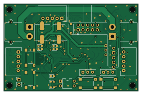
About the Odometry PCB
Odometry is an open source PCB design by Tomoshibi-technology, published on GitHub under the MIT license. It is a 2-layer board measuring 72 × 47 mm, with 41 components from 11 distinct parts.
Other key parts include the MAX3485. By type, the board carries 31 resistors, 9 capacitors and 1 IC.
From the project
燈のプロダクト達を動かしている基板開発用リポジトリ
Main components on the Odometry
Odometry bill of materials (BOM)
41 components, 11 distinct parts — part numbers from the project's BOM.
| Qty | Part | Footprint | Refs |
|---|---|---|---|
| 1 | MAX3485 | SOP-8_3.9x4.9mm_P1.27mm | U3 |
| 1 | 4.7UF 4.7uF | C_0603_1608Metric | C2 |
| 5 | 0.1UF 0.1uF | C_0402_1005Metric | C4, C14, C16, C18, C19 |
| 1 | 10UF 10uF | C_0805_2012Metric | C7 |
| 2 | 1UF 1uF | C_0402_1005Metric | C10, C17 |
| 17 | 10K 10k | R_0402_1005Metric | R1, R2, R3, R4, R5, R6, R8, R12 +9 |
| 9 | 1k | R_0402_1005Metric | R7, R9, R10, R11, R22, R28, R29, R30 +1 |
| 1 | 7.5K 7.5k | R_0603_1608Metric | R32 |
| 1 | 20K 20k | R_0402_1005Metric | R33 |
| 2 | 2.2K 2.2k | R_0402_1005Metric | R34, R35 |
| 1 | 120 | R_0402_1005Metric | R36 |
Odometry design files
The KiCad project lives in the Tomoshibi-technology/Tomoshibi_Circuit repository on GitHub; these links point at the commit this page was built from.
Odometry: common questions
How big is the Odometry PCB?
The Odometry measures 72 × 47 mm, has 2 copper layers and is 1.6 mm thick.
How many components are on the Odometry?
41 components, from 11 distinct parts, with part numbers taken from the project's own BOM. The full bill of materials is listed on this page.
Where can I download the Odometry design files?
From the Tomoshibi-technology/Tomoshibi_Circuit repository on GitHub, which has the KiCad layout, the schematic and the BOM; the links under Design files point to each one.
Can I use the Odometry design in my own project?
Yes, under the terms of its MIT license, which Tomoshibi-technology chose for the repository.
More boards in Tomoshibi_Circuit
 ESP32
ESP32ESP32
150 × 150 mm224 parts2LMIT0 STM32
STM32Common Control
110 × 120 mm219 parts2LMIT0 STM32
STM32Main
110 × 120 mm200 parts2LMIT0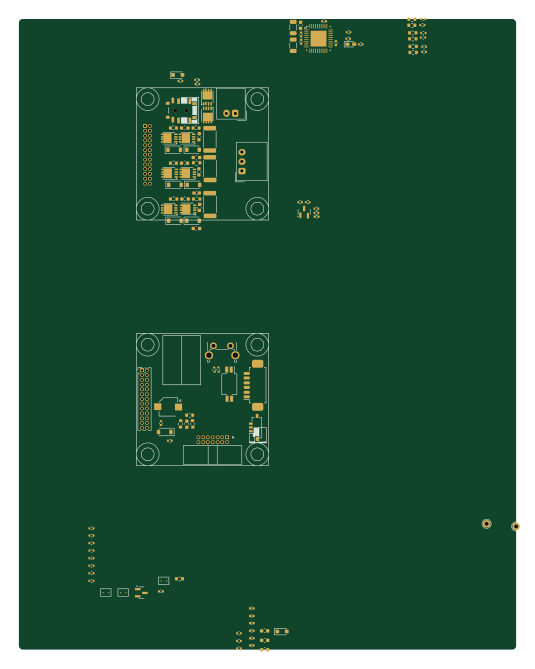 STM32
STM32BLDC Ver1
131.6 × 167 mm165 parts2LMIT0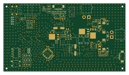 STM32
STM32Motordriver
125 × 70 mm131 parts2LMIT0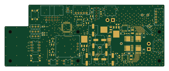 STM32
STM32MD
147 × 57 mm126 parts2LMIT0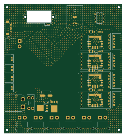
Power
110 × 120 mm91 parts2LMIT0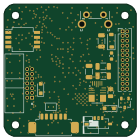
Control
35 × 35 mm68 parts4LMIT0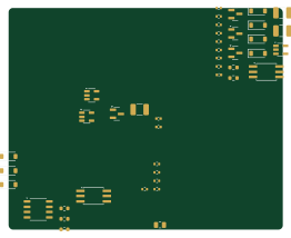
Ver1
65.3 × 52.7 mm42 parts2LMIT0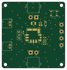
StepDown
55 × 58 mm20 parts2LMIT0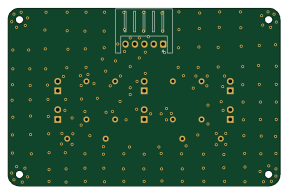
Line board
72 × 47 mm13 parts2LMIT0