
6x1A-BT2.0-4.35V-USB-C-charger

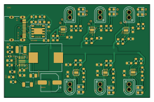
About the 6x1A-BT2.0-4.35V-USB-C-charger PCB
6x1A-BT2.0-4.35V-USB-C-charger is an open source PCB design by tomy983, published on GitHub. It is a 2-layer board measuring 55 × 35.2 mm, with 84 components from 26 distinct parts.
Other key parts include the LGS4056HDA-4.35, CH224K and TPS568215RNN. By type, the board carries 28 resistors, 13 diodes, 13 capacitors, 8 ICs, 7 connectors and 1 inductor.
It belongs with the power & battery designs in this gallery.
From the project
6 1S lipo cells charger with BT2.0 connectors - 1A charge current (each) - USB-C PD powered
12V via USB-C PD is requested. If the supply will comply 12V Vbus goes trough an 8A buck conveter to deliver 5V to each of 6 individual 4.35V 1A charger IC.
A green LED indicates 12V rail from PD present.
Green and red leds near each BT2.0 connector indicates charging status.
The BOM is made with JLCPCB component list in mind. Current production quote is 39€ for 2 pcs.
Main components on the 6x1A-BT2.0-4.35V-USB-C-charger
6x1A-BT2.0-4.35V-USB-C-charger bill of materials (BOM)
84 components, 26 distinct parts — part numbers from the project's BOM.
| Qty | Part | Footprint | Refs |
|---|---|---|---|
| 6 | LGS4056HDA-4.35 | DFN-8-1EP_2x2mm_P0.5mm_EP0.9x1.6mm | U1, U2, U3, U4, U5, U6 |
| 1 | CH224K | ESSOP10 | U7 |
| 1 | TPS568215RNN | Texas_RNN0018A | U8 |
| 6 | betafpv BT2.0 MALE Conn_01x02 | BT2.0 | J1, J2, J3, J4, J5, J6 |
| 1 | GT-USB-7010ASV USB_C_CONN | USB_C_Receptacle_G-Switch_GT-USB-7010ASV | J7 |
| 1 | GRM31C5C1H104JA01K 100n | C_1206_3216Metric | Cbst1 |
| 1 | GRM1555C1H221JA01J 220p | C_0402_1005Metric | Cff1 |
| 2 | GRM188R71H104KA93D 100n | C_0603_1608Metric | Cihf_ch1, Cihf_ch2 |
| 1 | GRM32ER71J106KA12L 10u | C_1210_3225Metric | Cin1 |
| 1 | 16SVPF180M 180u | CP_Elec_6.3x5.9 | Cout1 |
| 1 | GRM21BR61A226ME44L 22u | C_0805_2012Metric | Coutx1 |
| 1 | CC0603KRX7R9BB822 4.7u | C_0603_1608Metric | Creg1 |
| 1 | CC0603KRX7R9BB822 10n | C_0603_1608Metric | Css1 |
| 2 | 10K | R_0603_1608Metric | Rfbb1, Rpg1 |
| 1 | 73.2K | R_0603_1608Metric | Rfbt1 |
| 1 | 121K | R_0603_1608Metric | Rmh1 |
| 1 | 20K | R_0603_1608Metric | Rml1 |
| 7 | 19-217/GHC-YR1S2/3T GREEN | LED_0603_1608Metric | D1, D4, D6, D8, D10, D12, D13 |
| 6 | 19-213/R6W-BP2Q2B/3T RED | LED_0603_1608Metric | D2, D3, D5, D7, D9, D11 |
| 1 | YSPI1040-1R5M 1.6uH | L_Chilisin_BMRF00101040 | L1 |
Show 6 more
| Qty | Part | Footprint | Refs |
|---|---|---|---|
| 12 | 10U 10u | C_0603_1608Metric | C1, C2, C3, C4, C5, C6, C7, C8 +4 |
| 1 | CL10A105KB8NNNC 1u | C_0603_1608Metric | C13 |
| 6 | 1 | R_0603_1608Metric | R1, R8, R14, R20, R26, R32 |
| 20 | 1K | R_0603_1608Metric | R2, R3, R4, R7, R9, R10, R13, R15 +12 |
| 1 | 10K | R_0603_1608Metric | R101 |
| 1 | 24K | R_0603_1608Metric | R102 |
6x1A-BT2.0-4.35V-USB-C-charger design files
The KiCad project lives in the tomy983/6x1A-BT2.0-4.35V-USB-C-charger repository on GitHub; these links point at the commit this page was built from.
6x1A-BT2.0-4.35V-USB-C-charger: common questions
How big is the 6x1A-BT2.0-4.35V-USB-C-charger PCB?
The 6x1A-BT2.0-4.35V-USB-C-charger measures 55 × 35.2 mm, has 2 copper layers and is 1.6 mm thick.
How many components are on the 6x1A-BT2.0-4.35V-USB-C-charger?
84 components, from 26 distinct parts, with part numbers taken from the project's own BOM. The full bill of materials is listed on this page.
Where can I download the 6x1A-BT2.0-4.35V-USB-C-charger design files?
From the tomy983/6x1A-BT2.0-4.35V-USB-C-charger repository on GitHub, which has the KiCad layout, the schematic and the BOM; the links under Design files point to each one.
Can I use the 6x1A-BT2.0-4.35V-USB-C-charger design in my own project?
The repository has no license, so all rights stay with tomy983. Use it as a reference, and ask the author before reusing the design.
Similar boards

Display Carrier
AxxAxx
35.6 × 58.2 mm5 parts2LGPL-3.01.7k
ControllerCurrentShuntAddOn
stuartpittaway
26 × 16.9 mm9 parts2LCC-BY-NC-4.01.1k
TemperaturePCB PANEL
116 × 75.5 mm178 parts2LCC-BY-NC-4.01.1k
Module 16S PassiveBalanceAddOn
61 × 74 mm86 parts2LCC-BY-NC-4.01.1k
ProgrammingAdapter
10.5 × 83 mm3 parts2LCC-BY-NC-4.01.1k
Cube batteryboard
willem-pennings
95 × 95 mm4 parts2LGPL-3.01.1k