
Ram Tester

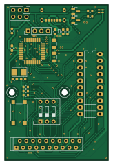
About the Ram Tester PCB
Ram Tester is an open source AVR/Arduino PCB design by tops4u, published on GitHub under the GPL-3.0 license. It is a 2-layer board measuring 39.8 × 59.4 mm, with 35 components from 24 distinct parts.
Its main chip is the ATMEGA328P-AU, from the AVR/Arduino family. Other key parts include the RAM / ZIF and ZIP Socket. By type, the board carries 14 resistors, 6 capacitors, 3 ICs, 3 connectors, 2 transistors and 2 switches.
It belongs with the retro computing designs in this gallery.
From the project
Ram Tester for vintage CBM Computer RAM Chips
This is the mixed SMD/through-hole version of the RAM Tester. SMD components are used for the main circuit; the ZIF socket, ZIP socket, DIP switch and pin headers are through-hole.
Notes: - J1 (display) and J2 (ICSP) are pin headers, not SMD — solder them as through-hole. - R1 and R6 are LED current limitors. The values above work with the Kingbright dual LED. If you substitute a different LED (e.g. from AliExpress), R6 may need to be 500–560 Ω depending on forward voltage.
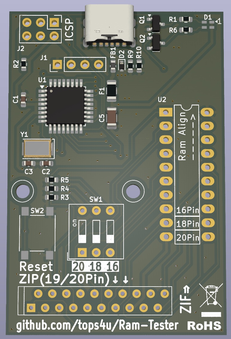
Main components on the Ram Tester
Ram Tester bill of materials (BOM)
35 components, 24 distinct parts — part numbers from the project's BOM.
| Qty | Part | Footprint | Refs |
|---|---|---|---|
| 1 | ATMEGA328P-AU ATmega328-P Microchip Technology | TQFP-32_7x7mm_P0.8mm | U1 |
| 1 | RAM / ZIF | DIP-20_W7.62mm_LongPads | U2 |
| 1 | ZIP Socket | ZIP-20 | U3 |
| 2 | BSS138 Onsemi | SOT-23 | Q1, Q2 |
| 1 | 445I32C16M00000 16MHZ CTS Electronics Components | Crystal_SMD_5032-2Pin_5.0x3.2mm | Y1 |
| 1 | Conn_01x04_Pin | PinHeader_1x04_P2.54mm_Vertical | J1 |
| 1 | ICSP | PinHeader_2x03_P2.54mm_Vertical | J2 |
| 1 | 6Pin SMD USB-C | USB_C_Receptacle_GCT_USB4125-xx-x-0190_6P_TopMnt_Horizontal | J3 |
| 1 | PTS12066V050 0.25A Eaton electronics | Fuse_1206_3216Metric | F1 |
| 1 | SW_DIP_x03 | SW_DIP_SPSTx03_Slide_9.78x9.8mm_W7.62mm_P2.54mm | SW1 |
| 1 | SW_Push | SW_Push_1P1T_NO_6x6mm_H9.5mm | SW2 |
| 1 | APTB1615SURKCGKC-F01 Kingbright | LED_SMD_RG_AKAK | D1 |
| 1 | CESDBLC5V0D5 | D_SOD-923 | D2 |
| 1 | CESDBLC5V0D5 | L_0603_1608Metric | FB1 |
| 3 | 06036C104MAZ2A 100nF kyocera avx | C_0603_1608Metric_Pad1.08x0.95mm_HandSolder | C1, C4, C7 |
| 2 | C0603C150K5GAC 12pF kemet | C_0603_1608Metric | C2, C3 |
| 1 | T491A106K006AT7280 10uF kyocera avx | C_1206_3216Metric | C5 |
| 1 | RT0603FRE13390RL 390R yageo | R_0603_1608Metric | R1 |
| 1 | RT0603FRE071KL 1k yageo | R_0603_1608Metric | R2 |
| 3 | AC0603FR-131ML 1M yageo | R_0603_1608Metric | R3, R4, R5 |
Show 4 more
| Qty | Part | Footprint | Refs |
|---|---|---|---|
| 1 | RT0603FRE13150RL 150R yageo | R_0603_1608Metric | R6 |
| 2 | RT0603DRD0747RL 47R yageo | R_0603_1608Metric | R7, R8 |
| 2 | RT0603FRD075K1L 5.1k yageo | R_0603_1608Metric | R9, R10 |
| 4 | RAVF164DJT47R0 47R SEI | R_Array_Concave_4x0603 | RN1, RN2, RN3, RN4 |
Ram Tester design files
The KiCad project lives in the tops4u/Ram-Tester repository on GitHub; these links point at the commit this page was built from.
Ram Tester: common questions
What microcontroller does the Ram Tester use?
The Ram Tester is built around the ATMEGA328P-AU, from the AVR/Arduino family.
How big is the Ram Tester PCB?
The Ram Tester measures 39.8 × 59.4 mm, has 2 copper layers and is 1.6 mm thick.
How many components are on the Ram Tester?
35 components, from 24 distinct parts, with part numbers taken from the project's own BOM. The full bill of materials is listed on this page.
Where can I download the Ram Tester design files?
From the tops4u/Ram-Tester repository on GitHub, which has the KiCad layout, the schematic and the BOM; the links under Design files point to each one.
Can I use the Ram Tester design in my own project?
Yes, under the terms of its GPL-3.0 license, which tops4u chose for the repository.
Can I test firmware for the Ram Tester without the hardware?
Yes. HardLabs builds a simulation of the board from its netlist and BOM, so you can run and debug AVR/Arduino firmware against it before you order a PCB.
More boards in Ram-Tester
Similar boards
 AVR/Arduino
ModuleV450
stuartpittaway
30 × 61.4 mm39 parts2LCC-BY-NC-4.01.1k AVR/Arduino
V4
30 × 50 mm38 parts2LCC-BY-NC-4.01.1k AVR/Arduino
Easyduino Atmega
Hanqaqa
68.8 × 53.6 mm35 parts4LCERN-OHL-P-2.0746 AVR/Arduino
Easyduino Atmega Nano
43.4 × 18 mm30 parts4LCERN-OHL-P-2.0746 AVR/Arduino
UsbGpib
xyphro
54 × 15 mm21 parts2LMIT683 AVR/Arduino
Lumberjack
peej
284.7 × 94.2 mm149 parts2LMIT402