
Solar smart station

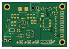
About the Solar smart station PCB
Solar smart station is an open source PCB design by truongduynhan, published on GitHub under the MIT license. It is a 4-layer board measuring 57.8 × 39.5 mm, with 81 components from 38 distinct parts.
Other key parts include the TBD, TLV73333PDBV, MSPM0C1104SDSGR and CSD25402Q3A. By type, the board carries 33 capacitors, 30 resistors, 5 ICs, 5 connectors, 2 transistors and 2 diodes.
It belongs with the power & battery designs in this gallery.
From the project
Solar charger with multiple inputs and automatic power paths - CI/CD with KiBot/KiCad
. ├─ Computations # Misc calculations ├─ HTML # HTML files for generated webpage ├─ Images # Pictures and renders │ ├─ kibotresources # External resources for KiBot │ ├─ colors # Color theme for KiCad │ ├─ fonts # Fonts used in the project │ ├─ scripts # External scripts used with KiBot │ └─ templates # Templates for KiBot generated reports │ ├─ kibotyaml # KiBot YAML config files ├─ KiRI # KiRI (PCB diff viewer) files │ ├─ lib # KiCad footprint and symbol libraries │ ├─ 3dmodels # Component 3D models │ ├─ libfp # Footprint libraries │ └─ lib_sym # Symbol libraries │ ├─ Logos # Logos │ ├─…
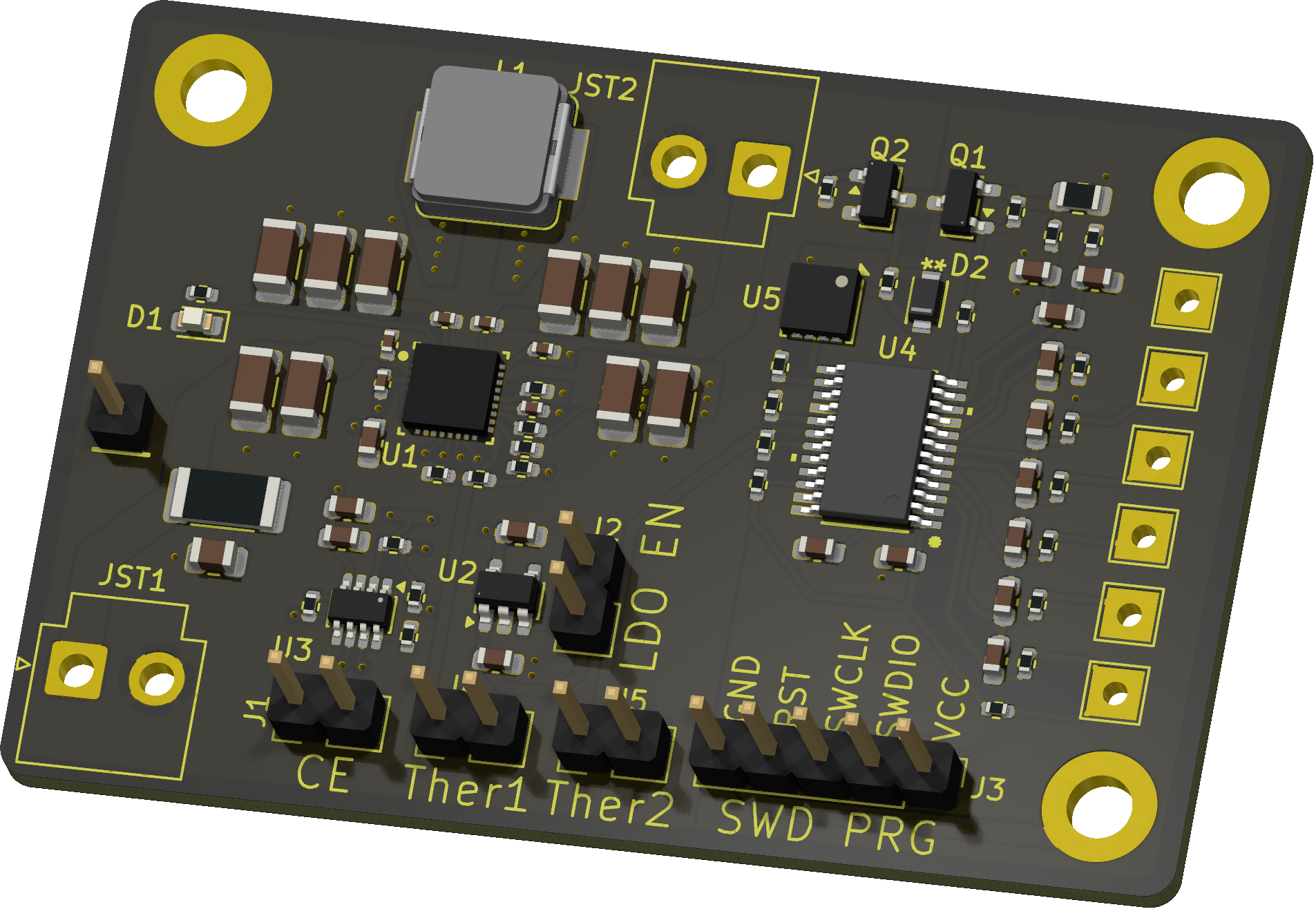
Main components on the Solar smart station
Solar smart station bill of materials (BOM)
81 components, 38 distinct parts — part numbers from the project's BOM.
| Qty | Part | Footprint | Refs |
|---|---|---|---|
| 1 | TBD BQ25672RQMR | RQM0029A-MFG | U1 |
| 1 | TLV73333PDBV | SOT-23-5 | U2 |
| 1 | MSPM0C1104SDSGR | TSOT-23-8-shrink | U3 |
| 1 | TBD BQ7791500PWR | PW24_TEX | U4 |
| 1 | CSD25402Q3A | VSON-8_3.3x3.3mm_P0.65mm_NexFET | U5 |
| 2 | AO3400A | SOT-23 | Q1, Q2 |
| 1 | CONN_01X02_PIN Conn_01x02_Pin | PinHeader_1x02_P2.54mm_Vertical | J1 |
| 1 | CONN_01X02_PIN LDO_EN | PinHeader_1x02_P2.54mm_Vertical | J2 |
| 1 | CONN_01X02_PIN Conn_01x05_Pin | PinHeader_1x05_P2.54mm_Vertical | J3 |
| 1 | CONN_01X02_PIN Thermistor_1 | PinHeader_1x02_P2.54mm_Vertical | J4 |
| 1 | CONN_01X02_PIN Thermistor_2 | PinHeader_1x02_P2.54mm_Vertical | J5 |
| 2 | CONN_01X02_PIN Conn_01x02_Socket | JST_VH_B2P-VH_1x02_P3.96mm_Vertical | JST1, JST2 |
| 1 | QON | PinHeader_1x01_P2.54mm_Vertical | TP1 |
| 1 | LED | LED_0603_1608Metric | D1 |
| 1 | RSX101VYM30FHTR Schottky_30V_1A | DIO_RB02_ROM | D2 |
| 1 | SPM6530T-1R0M120 1uH | L_Bourns_SRP7028A_7.3x6.6mm | L1 |
| 1 | TBD 2.2uF | C_0805_2012Metric | C1 |
| 3 | TBD 0.1uF | C_0402_1005Metric | C2, C9, C10 |
| 10 | TBD 10uF | C_1206_3216Metric | C3, C4, C11, C12, C13, C14, C15, C16 +2 |
| 2 | TBD 47nF | C_0402_1005Metric | C5, C7 |
Show 18 more
| Qty | Part | Footprint | Refs |
|---|---|---|---|
| 2 | TBD 4.7uF | C_0603_1608Metric | C6, C21 |
| 1 | TBD 1nF | C_0402_1005Metric | C8 |
| 12 | TBD 0.1uF | C_0603_1608Metric | C19, C20, C22, C23, C24, C25, C26, C27 +4 |
| 2 | TBD 1uF | C_0603_1608Metric | C29, C30 |
| 1 | TBD 2R-1W | R_2010_5025Metric | R1 |
| 6 | TBD 4.7kR | R_0402_1005Metric | R2, R9, R10, R11, R12, R23 |
| 1 | TBD 5.24kR | R_0402_1005Metric | R3 |
| 1 | TBD 30.31kR | R_0402_1005Metric | R4 |
| 1 | TBD 6.04kR | R_0402_1005Metric | R5 |
| 3 | TBD 100R | R_0402_1005Metric | R6, R20, R22 |
| 1 | TBD 127kR | R_0402_1005Metric | R7 |
| 2 | TBD 100kR | R_0402_1005Metric | R8, R28 |
| 7 | TBD 1kR | R_0402_1005Metric | R13, R14, R15, R16, R17, R18, R19 |
| 1 | TBD 10mR | R_0805_2012Metric | R21 |
| 2 | TBD 1MegR | R_0402_1005Metric | R24, R25 |
| 1 | TBD 3.3MegR | R_0402_1005Metric | R26 |
| 2 | TBD 10kR | R_0402_1005Metric | R27, R30 |
| 1 | TBD 450kR | R_0402_1005Metric | R29 |
Solar smart station design files
The KiCad project lives in the truongduynhan/solar_smart_station repository on GitHub; these links point at the commit this page was built from.
Solar smart station: common questions
How big is the Solar smart station PCB?
The Solar smart station measures 57.8 × 39.5 mm, has 4 copper layers and is 1.66 mm thick.
How many components are on the Solar smart station?
81 components, from 38 distinct parts, with part numbers taken from the project's own BOM. The full bill of materials is listed on this page.
Where can I download the Solar smart station design files?
From the truongduynhan/solar_smart_station repository on GitHub, which has the KiCad layout, the schematic and the BOM; the links under Design files point to each one.
Can I use the Solar smart station design in my own project?
Yes, under the terms of its MIT license, which truongduynhan chose for the repository.
Similar boards

EinkPDA screen
TalismanDesign
95 × 54 mm27 parts2LApache-2.02.0k
Stack chan
stack-chan
50 × 50 mm33 parts2LApache-2.01.7k
Display Carrier
AxxAxx
35.6 × 58.2 mm5 parts2LGPL-3.01.7k
ProgrammingAdapter
stuartpittaway
10.5 × 83 mm3 parts2LCC-BY-NC-4.01.1k
TemperaturePCB PANEL
116 × 75.5 mm178 parts2LCC-BY-NC-4.01.1k
Module 16S PassiveBalanceAddOn
61 × 74 mm86 parts2LCC-BY-NC-4.01.1k