
Relay Module

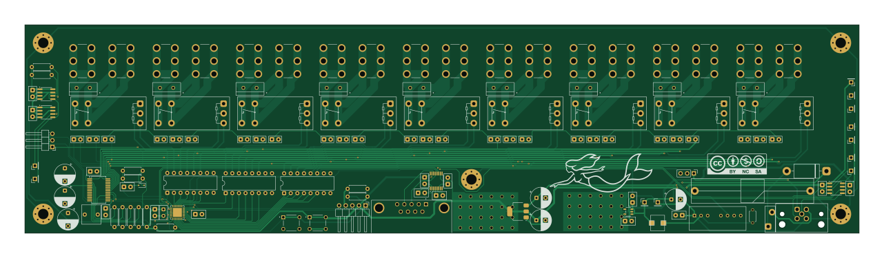
About the Relay Module
Relay Module is an open source STM32 PCB design by Tuskar-Marine, published on GitHub. It is a 4-layer board measuring 320 × 80 mm, with 134 components from 53 distinct parts.
Its main chip is the MAX3232, from the STM32 family. Other key parts include the ISO1044BD, LM1117MP-5.0, STM32C092KCT6, IS31FL3731-SA and FM24CL64B-G. By type, the board carries 38 diodes, 25 capacitors, 12 resistors, 11 test points, 10 ICs and 3 switches.
From the project
All tools for the Mermaid's Rest open sailing tools
All tools for the Mermaid's Rest open sailing tools
Note: Patches and PRs are welcome, but at this stage of the project, I need to be able to understand / fix the code. Good comments and references to reading material will be grately appreciated! ^_^
If/when the project gets outside interest, I'll step out of the way of the much more talented folks.
Main components on the Relay Module
Relay Module bill of materials (BOM)
134 components, 53 distinct parts — part numbers from the project's BOM.
| Qty | Part | Footprint | Refs |
|---|---|---|---|
| 1 | ISO1044BD | SOIC-8_3.9x4.9mm_P1.27mm | U1 |
| 1 | LM1117MP-5.0 MAX3232 | TSSOP-16_4.4x5mm_P0.65mm | U2 |
| 1 | MAX3232 STM32C092KCT6 | QFN-32-1EP_5x5mm_P0.5mm_EP3.45x3.45mm | U3 |
| 1 | STM32C092KCT6 ULN2003A | DIP-16_W7.62mm | U4 |
| 1 | IS31FL3731-SA ULN2003A | DIP-16_W7.62mm | U5 |
| 1 | FM24CL64B-G ULN2003A | DIP-16_W7.62mm | U6 |
| 2 | FM24CL64B-G | SOIC-8_3.9x4.9mm_P1.27mm | U8, U10 |
| 1 | IS31FL3731-SA | SSOP-28_5.3x10.2mm_P0.65mm | U9 |
| 1 | LM1117MP-5.0 | SOT-223-3_TabPin2 | U15 |
| 1 | Future Bond | PinHeader_1x03_P2.54mm_Vertical | J1 |
| 1 | Program Header | PinHeader_1x05_P2.54mm_Horizontal | J3 |
| 1 | ~ | Amphenol_L77SDE09SA4CH4F | DE1 |
| 1 | NCV8730ASN500T1G ~ | G5RL-K1A | LR1 |
| 8 | ~ | G5RL-K1A | LR2, LR3, LR4, LR5, LR6, LR7, LR8, LR9 |
| 1 | NCV8730ASN500T1G | TSOP-5_483_OSI | LR12 |
| 1 | ~ | M12B-05PMMR | N2K1 |
| 1 | SPBW06F-05 | SPBW06F05 | PS2 |
| 1 | PTC | AHEF100 | PTC2 |
| 1 | SW_MEC_5G Status Switch | PinHeader_1x03_P2.54mm_Horizontal | SW1 |
| 2 | SW_MEC_5G | SW_TS03-66-50-BK-160-LCR-D-67 | SW3, SW4 |
Show 33 more
| Qty | Part | Footprint | Refs |
|---|---|---|---|
| 18 | Keystone Electronics 7799 | Keystone 7799 | TB1, TB2, TB3, TB4, TB5, TB6, TB7, TB8 +10 |
| 1 | TP_VRAW | PinHeader_1x01_P2.54mm_Vertical | TP1 |
| 3 | GND_SHIP | PinHeader_1x01_P2.54mm_Vertical | TP2, TP6, TP13 |
| 1 | N2K_RX | PinHeader_1x01_P2.54mm_Vertical | TP3 |
| 1 | N2K_TX | PinHeader_1x01_P2.54mm_Vertical | TP4 |
| 2 | +5V_SHIP | PinHeader_1x01_P2.54mm_Vertical | TP5, TP12 |
| 1 | +5V | PinHeader_1x01_P2.54mm_Vertical | TP7 |
| 1 | GND | PinHeader_1x01_P2.54mm_Vertical | TP8 |
| 1 | +3.3V | PinHeader_1x01_P2.54mm_Vertical | TP9 |
| 1 | PESD3V3L1BA | D_SOD-323 | TVS1 |
| 14 | LED | WP383SURDTK | D1, D2, D3, D4, D5, D15, D16, D17 +6 |
| 13 | LED_45DEG LED | WP383SURDTK | D6, D7, D8, D9, D10, D11, D12, D13 +5 |
| 1 | LED_45DEG VT3045BP-M3/4W | Vishay VT3045BP-M3_4W_VIS | D50 |
| 8 | VT3045BP-M3/4W | Vishay VT3045BP-M3_4W_VIS | D51, D52, D53, D54, D55, D56, D57, D58 |
| 1 | 1N5822 | D_DO-201AD_P15.24mm_Horizontal | D145 |
| 1 | SLD15-018 SLD22-018 | DIOAD4425W136L885D885 | D146 |
| 9 | 0.1UF 0.1uF | RCE5C1H104J2A2H03B | C1, C2, C10, C11, C12, C13, C22, C23 +1 |
| 5 | 0.1UF 0.1μF | RCE5C1H104J2A2H03B | C3, C4, C15, C20, C21 |
| 3 | 10UF 10uF | CP_Radial_D8.0mm_P3.50mm | C5, C8, C9 |
| 1 | TDK FA28NP01H152JNU06 | TDK CAPRB500W50L400T250H550 | C6 |
| 2 | 0.1uF | RCE5C1H104J2A2H03B | C7, C25 |
| 1 | 4.7UF 4.7μF | RCER71E475K2A2H03B | C14 |
| 3 | 100UF 100μF | CP_Radial_D8.0mm_P5.00mm | C16, C17, C18 |
| 1 | 1UF 1μF | C_Rect_L7.2mm_W7.2mm_P5.00mm_FKS2_FKP2_MKS2_MKP2 | C19 |
| 4 | 4.7K | R_Axial_DIN0207_L6.3mm_D2.5mm_P7.62mm_Horizontal | R1, R2, R3, R5 |
| 1 | 100K | R_Axial_DIN0207_L6.3mm_D2.5mm_P7.62mm_Horizontal | R4 |
| 1 | 3.3K | R_Axial_DIN0207_L6.3mm_D2.5mm_P7.62mm_Horizontal | R6 |
| 1 | 10K | R_Axial_DIN0207_L6.3mm_D2.5mm_P7.62mm_Horizontal | R7 |
| 1 | 147 10K | R_Axial_DIN0207_L6.3mm_D2.5mm_P7.62mm_Horizontal | R8 |
| 1 | 10K | R_Axial_DIN0207_L6.3mm_D2.5mm_P7.62mm_Horizontal | R9 |
| 1 | 10K 3.3K | R_Axial_DIN0207_L6.3mm_D2.5mm_P7.62mm_Horizontal | R10 |
| 1 | 63.4 3.3K | R_Axial_DIN0207_L6.3mm_D2.5mm_P7.62mm_Horizontal | R11 |
| 1 | 475 | R_Axial_DIN0207_L6.3mm_D2.5mm_P7.62mm_Horizontal | R68 |
Relay Module design files
The KiCad project lives in the Tuskar-Marine/hardware repository on GitHub; these links point at the commit this page was built from.
Relay Module: common questions
What microcontroller does the Relay Module use?
The Relay Module is built around the MAX3232, from the STM32 family.
How big is the Relay Module?
The Relay Module measures 320 × 80 mm, has 4 copper layers and is 1.659981 mm thick.
How many components are on the Relay Module?
134 components, from 53 distinct parts, with part numbers taken from the project's own BOM. The full bill of materials is listed on this page.
Where can I download the Relay Module design files?
From the Tuskar-Marine/hardware repository on GitHub, which has the KiCad layout, the schematic and the BOM; the links under Design files point to each one.
Can I use the Relay Module design in my own project?
The repository has no license, so all rights stay with Tuskar-Marine. Use it as a reference, and ask the author before reusing the design.
Can I test firmware for the Relay Module without the hardware?
Yes. HardLabs builds a simulation of the board from its netlist and BOM, so you can run and debug STM32 firmware against it before you order a PCB.
More boards in hardware
 STM32
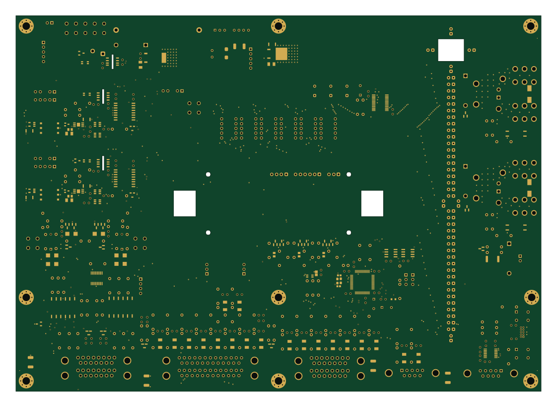
Muirgen Main Control Unit
280 × 200 mm381 parts4LNo license6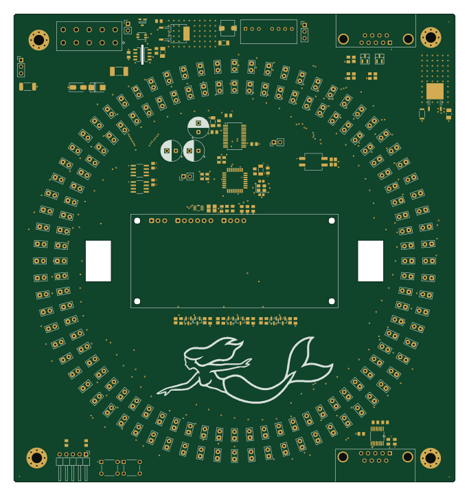 STM32
2-Ring Compass Rose
170 × 180 mm238 parts4LNo license6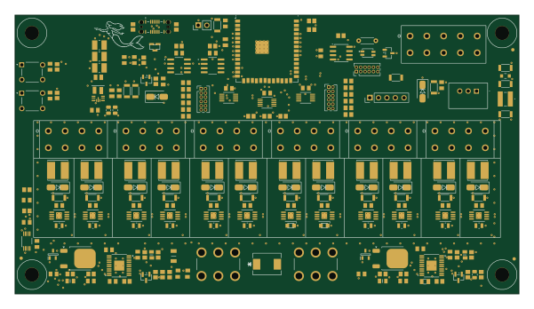 ESP32
Masthead Controller
150 × 83 mm209 parts4LNo license6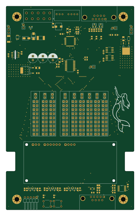 STM32
Battery Display
110 × 175.3 mm187 parts4LNo license6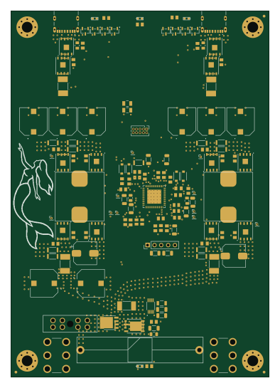
USB-C PD 2x 100W
96 × 136 mm116 parts4LNo license6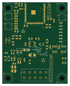 ESP32
N2K Transceiver
60 × 75 mm68 parts4LNo license6
Similar boards
 STM32
LumenPnP Motherboard
opulo-inc
149 × 95 mm296 parts4LCC-BY-SA-4.03.7k STM32
Type g
google
169 × 30 mm24 parts2LApache-2.02.9k STM32
Main panel
234 × 84 mm26 parts4LApache-2.02.9k STM32
Base
52.3 × 52.3 mm36 parts2LApache-2.02.9k STM32
Type a
150 × 30 mm14 parts2LApache-2.02.9k STM32
Type c
188 × 30 mm17 parts2LApache-2.02.9k