
5Pole RF Toggle

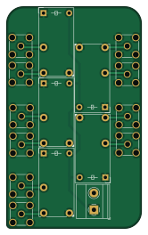
About the 5Pole RF Toggle PCB
5Pole RF Toggle is an open source PCB design by twfth9, published on GitHub under the GPL-3.0 license. It is a 2-layer board measuring 40 × 65.9 mm, with 16 components from 3 distinct parts.
By type, the board carries 11 connectors and 5 relays.
5Pole RF Toggle bill of materials (BOM)
16 components, 3 distinct parts.
| Qty | Part | Footprint | Refs |
|---|---|---|---|
| 10 | SMA Connector | SMA_Amphenol_132134-11_Vertical | J0, J1, J2, J3, J4, J5, J6, J7 +2 |
| 1 | Screw_Terminal_01x02 | TerminalBlock_Phoenix_MKDS-1,5-2_1x02_P5.00mm_Horizontal | J10 |
| 5 | FINDER-32.21-x000 | Relay_SPDT_Finder_32.21-x000 | K01, K23, K45, K67, K89 |
5Pole RF Toggle design files
The KiCad project lives in the twfth9/Kenwood-Handset-Switch-PCB repository on GitHub; these links point at the commit this page was built from.
5Pole RF Toggle: common questions
How big is the 5Pole RF Toggle PCB?
The 5Pole RF Toggle measures 40 × 65.9 mm, has 2 copper layers and is 1.6 mm thick.
How many components are on the 5Pole RF Toggle?
16 components, from 3 distinct parts. The full bill of materials is listed on this page.
Where can I download the 5Pole RF Toggle design files?
From the twfth9/Kenwood-Handset-Switch-PCB repository on GitHub, which has the KiCad layout and the schematic; the links under Design files point to each one.
Can I use the 5Pole RF Toggle design in my own project?
Yes, under the terms of its GPL-3.0 license, which twfth9 chose for the repository.
More boards in Kenwood-Handset-Switch-PCB
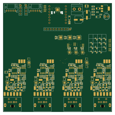 Microchip SAM
DATA Switcher
100 × 100 mm667 parts4LGPL-3.00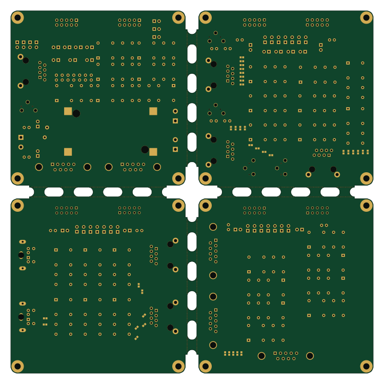
InterfaceModule
187 × 187 mm243 parts2LGPL-3.00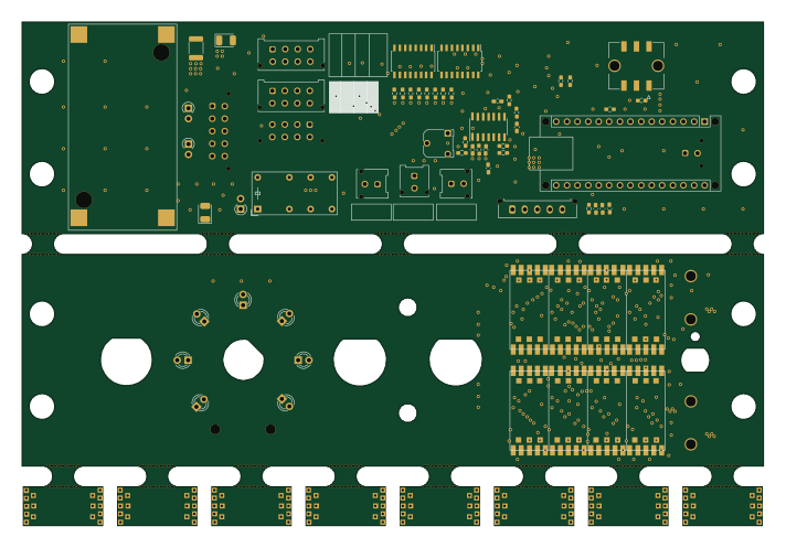
1-DIN Control Panel
177.8 × 120.9 mm82 parts2LGPL-3.00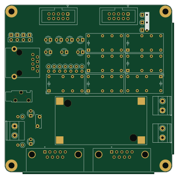
Main-GPSSwitching
91 × 91 mm72 parts2LGPL-3.00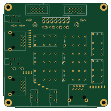
MicSwitch
91 × 91 mm63 parts2LGPL-3.00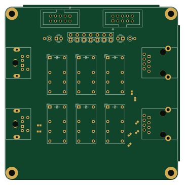
DataSwitching
91 × 91 mm55 parts2LGPL-3.00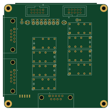
COMSwitching
91 × 91 mm52 parts2LGPL-3.00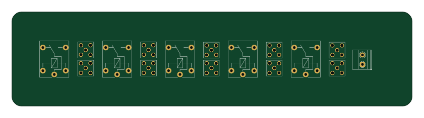
KrakenSDR AntDisconnect ThruThin
210 × 49.5 mm16 parts2LGPL-3.00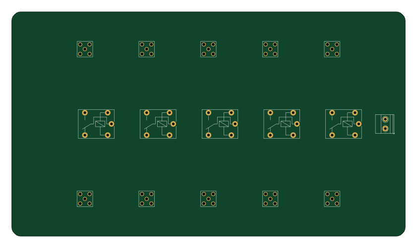
KrakenSDR AntDisconnect Thru
210 × 119.9 mm16 parts2LGPL-3.00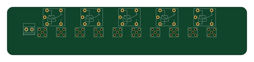
KrakenSDR AntDisconnect Edge
210 × 42.2 mm16 parts2LGPL-3.00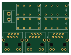
KenwoodHandsetSwitch
57.6 × 43.5 mm8 parts2LGPL-3.00