
Phase3-backplane

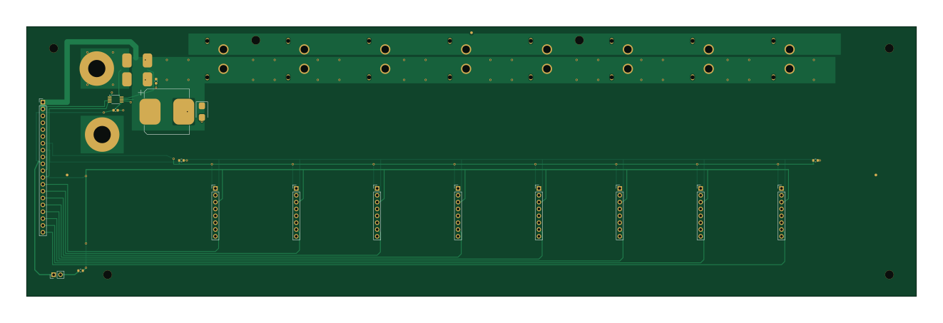
About the Phase3-backplane PCB
Phase3-backplane is an open source PCB design by udaravima, published on GitHub under the GPL-3.0 license. It is a 2-layer board measuring 330 × 100 mm, with 28 components from 26 distinct parts.
Other key parts include the INA228AIDGSR. By type, the board carries 18 connectors, 3 capacitors, 3 resistors, 1 IC and 1 diode.
It belongs with the power & battery designs in this gallery.
From the project
A modular, rack-style DC power supply: up to 8 hot-pluggable 600 W buck modules on a shared DC input bus, coordinated by a central manager over CAN. Each channel is a self-contained analog CV/CC supply with bench-grade precision, usable for lab work, bulk DC power, and battery ch
A modular, rack-style DC power supply: up to 8 hot-pluggable 600 W buck modules on a shared DC input bus, coordinated by a central manager over CAN. Each channel is a self-contained analog CV/CC supply with bench-grade precision, usable for lab work, bulk DC power, and battery charging.
- Phase 0 — design docs: complete (01–07). - Phase-1 schematic: complete (v1) and machine-verified — 7 generated sheets, 137 components; every net asserted against the intended net table, every footprint pad-checked; vendor symbols/footprints datasheet-vetted. Audited with the kicad-happy analyzers + ngspice…
Main components on the Phase3-backplane
Phase3-backplane bill of materials (BOM)
28 components, 26 distinct parts — part numbers from the project's BOM.
| Qty | Part | Footprint | Refs |
|---|---|---|---|
| 1 | INA228AIDGSR INA228 TI | VSSOP-10_3x3mm_P0.5mm | U1 |
| 1 | MANAGER | PinHeader_1x20_P2.54mm_Vertical | J1 |
| 1 | E-STOP NC (jumper if absent) | PinHeader_1x02_P2.54mm_Vertical | J2 |
| 1 | XT60PW-F SLOT0 XT60PW-F Amass | XT60PW-F | J10 |
| 1 | XT60PW-F SLOT1 XT60PW-F Amass | XT60PW-F | J11 |
| 1 | XT60PW-F SLOT2 XT60PW-F Amass | XT60PW-F | J12 |
| 1 | XT60PW-F SLOT3 XT60PW-F Amass | XT60PW-F | J13 |
| 1 | XT60PW-F SLOT4 XT60PW-F Amass | XT60PW-F | J14 |
| 1 | XT60PW-F SLOT5 XT60PW-F Amass | XT60PW-F | J15 |
| 1 | XT60PW-F SLOT6 XT60PW-F Amass | XT60PW-F | J16 |
| 1 | XT60PW-F SLOT7 XT60PW-F Amass | XT60PW-F | J17 |
| 1 | SLOT0 SIG | PinHeader_1x08_P2.54mm_Vertical | J20 |
| 1 | SLOT1 SIG | PinHeader_1x08_P2.54mm_Vertical | J21 |
| 1 | SLOT2 SIG | PinHeader_1x08_P2.54mm_Vertical | J22 |
| 1 | SLOT3 SIG | PinHeader_1x08_P2.54mm_Vertical | J23 |
| 1 | SLOT4 SIG | PinHeader_1x08_P2.54mm_Vertical | J24 |
| 1 | SLOT5 SIG | PinHeader_1x08_P2.54mm_Vertical | J25 |
| 1 | SLOT6 SIG | PinHeader_1x08_P2.54mm_Vertical | J26 |
| 1 | SLOT7 SIG | PinHeader_1x08_P2.54mm_Vertical | J27 |
| 2 | BVS-M-R0005 0m5 3920 Isabellenhuette | R3920_BVS | RS1, RS2 |
Show 6 more
| Qty | Part | Footprint | Refs |
|---|---|---|---|
| 1 | SMBJ33A | D_SMB | D5 |
| 2 | 100N 100n | C_0603_1608Metric | C1, C3 |
| 1 | 470U/50V 470u/50V | CP_Elec_16x17.5 | C2 |
| 1 | 1K | R_0603_1608Metric | R1 |
| 1 | 120R slot0-end | R_0603_1608Metric | R2 |
| 1 | 120R slot7-end | R_0603_1608Metric | R3 |
Phase3-backplane design files
The KiCad project lives in the udaravima/Lab_Bench repository on GitHub; these links point at the commit this page was built from.
Phase3-backplane: common questions
How big is the Phase3-backplane PCB?
The Phase3-backplane measures 330 × 100 mm, has 2 copper layers and is 1.6 mm thick.
How many components are on the Phase3-backplane?
28 components, from 26 distinct parts, with part numbers taken from the project's own BOM. The full bill of materials is listed on this page.
Where can I download the Phase3-backplane design files?
From the udaravima/Lab_Bench repository on GitHub, which has the KiCad layout, the schematic and the BOM; the links under Design files point to each one.
Can I use the Phase3-backplane design in my own project?
Yes, under the terms of its GPL-3.0 license, which udaravima chose for the repository.
More boards in Lab_Bench
Similar boards

Display Carrier
AxxAxx
35.6 × 58.2 mm5 parts2LGPL-3.01.7k
ControllerCurrentShuntAddOn
stuartpittaway
26 × 16.9 mm9 parts2LCC-BY-NC-4.01.1k
TemperaturePCB PANEL
116 × 75.5 mm178 parts2LCC-BY-NC-4.01.1k
Module 16S PassiveBalanceAddOn
61 × 74 mm86 parts2LCC-BY-NC-4.01.1k
ProgrammingAdapter
10.5 × 83 mm3 parts2LCC-BY-NC-4.01.1k
Cube batteryboard
willem-pennings
95 × 95 mm4 parts2LGPL-3.01.1k