
SEGA-Game-Gear to-RGB-TV

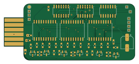
About the SEGA-Game-Gear to-RGB-TV PCB
SEGA-Game-Gear to-RGB-TV is an open source PCB design by Ugly-Mug, published on GitHub under the CC-BY-SA-4.0 license. It is a 2-layer board measuring 70 × 30 mm, with 42 components from 16 distinct parts.
Other key parts include the 74HC374, 74HC74 and 74HC04. By type, the board carries 27 resistors, 6 ICs, 6 transistors and 3 capacitors.
It belongs with the retro computing designs in this gallery.
From the project
Schematics and circuit board to output video from the SEGA Game Gear to a TV via the RGBS video standard (using a Nintendo Multi-out)
I added a Nintendo multi-out connector to the board so I could use cables I already owned for easy testing, however, it's straightforward to wire up your chosen/custom cable to the enlarged pads on the board.
Included in this repository are: 1. Schematics (KiCad) 2. PCB files (KiCad) 3. Production files including: - Gerber files - BOM file (Bill of Materials) - Placement file
Main components on the SEGA-Game-Gear to-RGB-TV
SEGA-Game-Gear to-RGB-TV bill of materials (BOM)
42 components, 16 distinct parts — part numbers from the project's BOM.
| Qty | Part | Footprint | Refs |
|---|---|---|---|
| 3 | 74HC374 | SOP-20_7.5x12.8mm_P1.27mm | U1, U2, U3 |
| 2 | 74HC74 | SOIC-14_3.9x8.7mm_P1.27mm | U4, U5 |
| 1 | 74HC04 | SOIC-14_3.9x8.7mm_P1.27mm | U6 |
| 3 | BC858 | SOT-23 | Q1, Q3, Q5 |
| 3 | BC848 | SOT-23 | Q2, Q4, Q6 |
| 2 | 100N 100n | C_0603_1608Metric_Pad1.08x0.95mm_HandSolder | C1, C2 |
| 1 | 100µ | CP_Elec_6.3x5.2 | C3 |
| 3 | 2K7 2k7 | R_0603_1608Metric_Pad0.98x0.95mm_HandSolder | R1, R21, R31 |
| 3 | 5K6 5k6 | R_0603_1608Metric_Pad0.98x0.95mm_HandSolder | R2, R22, R32 |
| 3 | 11K 11k | R_0603_1608Metric_Pad0.98x0.95mm_HandSolder | R3, R23, R33 |
| 3 | 22K 22k | R_0603_1608Metric_Pad0.98x0.95mm_HandSolder | R4, R24, R34 |
| 3 | 820 | R_0603_1608Metric_Pad0.98x0.95mm_HandSolder | R5, R25, R35 |
| 3 | 6K8 6k8 | R_0603_1608Metric_Pad0.98x0.95mm_HandSolder | R6, R26, R36 |
| 3 | 1K2 1k2 | R_0603_1608Metric_Pad0.98x0.95mm_HandSolder | R7, R27, R37 |
| 3 | 1k | R_0603_1608Metric_Pad0.98x0.95mm_HandSolder | R8, R28, R38 |
| 3 | 75 | R_0603_1608Metric_Pad0.98x0.95mm_HandSolder | R9, R29, R39 |
SEGA-Game-Gear to-RGB-TV design files
The KiCad project lives in the Ugly-Mug/SEGA-Game-Gear-to-RGB-TV repository on GitHub; these links point at the commit this page was built from.
SEGA-Game-Gear to-RGB-TV: common questions
How big is the SEGA-Game-Gear to-RGB-TV PCB?
The SEGA-Game-Gear to-RGB-TV measures 70 × 30 mm, has 2 copper layers and is 1 mm thick.
How many components are on the SEGA-Game-Gear to-RGB-TV?
42 components, from 16 distinct parts, with part numbers taken from the project's own BOM. The full bill of materials is listed on this page.
Where can I download the SEGA-Game-Gear to-RGB-TV design files?
From the Ugly-Mug/SEGA-Game-Gear-to-RGB-TV repository on GitHub, which has the KiCad layout, the schematic and the BOM; the links under Design files point to each one.
Can I use the SEGA-Game-Gear to-RGB-TV design in my own project?
Yes, under the terms of its CC-BY-SA-4.0 license, which Ugly-Mug chose for the repository.
Similar boards
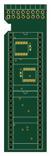
Amiga External
hoglet67
21.9 × 76.7 mm6 parts2LGPL-3.01.0k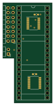
Atari pickup
26.4 × 53.9 mm7 parts2LGPL-3.01.0k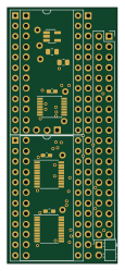
Deniseadapter
26.7 × 62.2 mm16 parts2LGPL-3.01.0k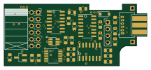
Analog
53.9 × 23.2 mm33 parts2LGPL-3.01.0k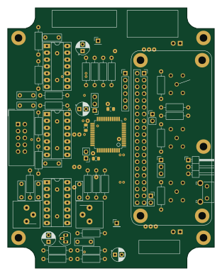
Rgb to hdmi
77 × 97 mm67 parts2LGPL-3.01.0k
Buffer
53.9 × 23.2 mm13 parts2LGPL-3.01.0k