
Speedy Breakout Board

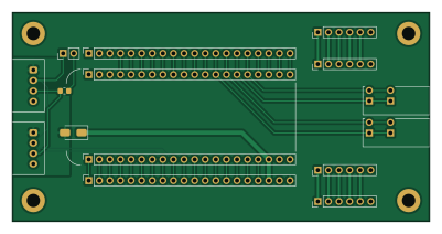
About the Speedy Breakout Board
Speedy Breakout Board is an open source PCB design by UofA-SPEAR, published on GitHub. It is a 2-layer board measuring 100 × 50 mm, with 9 components from 7 distinct parts.
By type, the board carries 7 connectors, 1 diode and 1 resistor.
It belongs with the dev boards & breakouts designs in this gallery.
From the project
A place for SPEAR PCBs
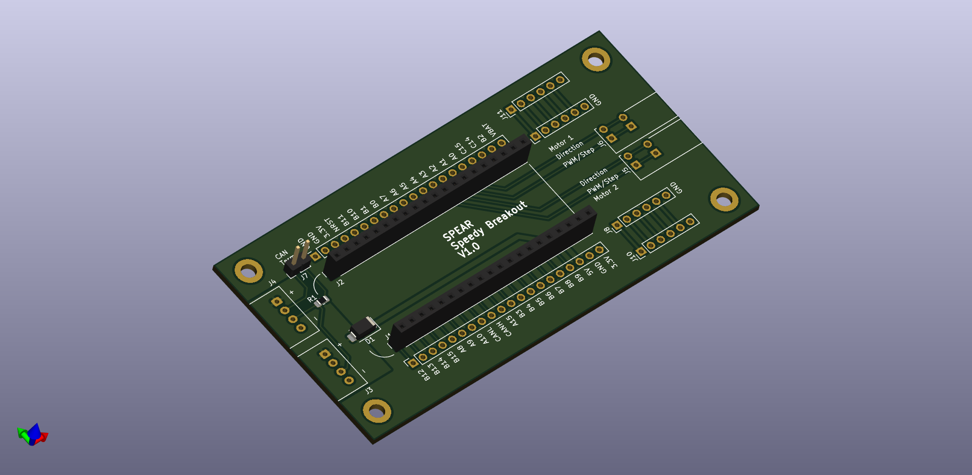
Speedy Breakout Board bill of materials (BOM)
9 components, 7 distinct parts.
| Qty | Part | Footprint | Refs |
|---|---|---|---|
| 2 | Pin Socket 1x20 | PinSocket_1x20_P2.54mm_Vertical | J1, J2 |
| 2 | Molex Mini-Lock 53426 | Molex_Mini-Lock_53426-0410_1x04_P2.50mm_Horizontal | J3, J4 |
| 1 | CUI TLB009-254 | TerminalBlock_CUI_TBL009-254-02_1x04_P2.54mm_Horizontal | J5 |
| 1 | CUI TBL009-254 | TerminalBlock_CUI_TBL009-254-02_1x04_P2.54mm_Horizontal | J6 |
| 1 | Conn_01x02 | PinHeader_1x02_P2.54mm_Vertical | J7 |
| 1 | D | D_SMA | D1 |
| 1 | 120 | R_0805_2012Metric_Pad1.20x1.40mm_HandSolder | R1 |
Speedy Breakout Board design files
The KiCad project lives in the UofA-SPEAR/pcb_designs repository on GitHub; these links point at the commit this page was built from.
Speedy Breakout Board: common questions
How big is the Speedy Breakout Board?
The Speedy Breakout Board measures 100 × 50 mm, has 2 copper layers and is 1.6 mm thick.
How many components are on the Speedy Breakout Board?
9 components, from 7 distinct parts. The full bill of materials is listed on this page.
Where can I download the Speedy Breakout Board design files?
From the UofA-SPEAR/pcb_designs repository on GitHub, which has the KiCad layout and the schematic; the links under Design files point to each one.
Can I use the Speedy Breakout Board design in my own project?
The repository has no license, so all rights stay with UofA-SPEAR. Use it as a reference, and ask the author before reusing the design.
More boards in pcb_designs
Arm controller single v1.1
100 × 50 mm51 parts2LNo license3
Comp PDU
100 × 70 mm50 parts2LNo license3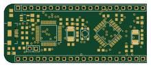 STM32
STM32Green Pill stlink
55 × 23 mm42 parts2LNo license3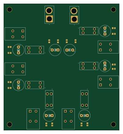
Sub sys pdu
100 × 110 mm38 parts2LNo license3
Buck module 5v
25 × 25 mm28 parts2LNo license3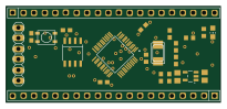 STM32
STM32Speedy barebone
51.2 × 23 mm23 parts2LNo license3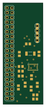
IMU
21.3 × 53.7 mm17 parts2LNo license3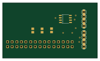
Communication hub
51.7 × 30.5 mm7 parts2LNo license3
As5600 adapter
16 × 16 mm6 parts2LNo license3
Canbus basic
20 × 4 mm5 parts2LNo license3
Similar boards

134pin 7-967288-1
rusefi
139.7 × 73.7 mm38 parts2LGPL-3.01.2k
Breakout 112pin Connector
174 × 58 mm39 parts2LGPL-3.01.2k
Breakout 60pin EEC-IV
139.7 × 62.2 mm15 parts2LGPL-3.01.2k
Eecv breakout
140.8 × 53.7 mm9 parts4LGPL-3.01.2k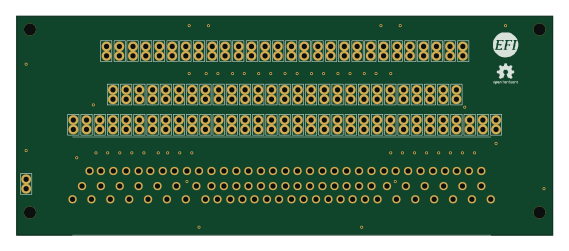
88 Pin Vag Breakout
142 × 58 mm91 parts2LGPL-3.01.2k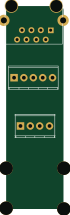
Rj45 breakout
rene-dev
15.2 × 53.8 mm3 parts2LGPL-3.0979