
169 gateway

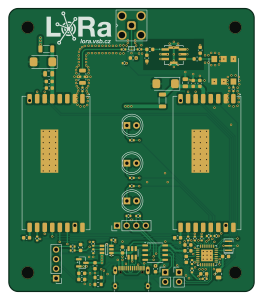
About the 169 gateway PCB
169 gateway is an open source AVR/Arduino PCB design by vsb-fei-440, published on GitHub under the MIT license. It is a 4-layer board measuring 65 × 75 mm, with 64 components from 25 distinct parts.
Its main chip is the ATMEGA328P-M, from the AVR/Arduino family. Other key parts include the TPS2553DDBVR, USBLC6-2SC6, CH340N, BGS12P2L6E6327 and MCP1700X-330XXTT. By type, the board carries 28 capacitors, 22 resistors, 6 ICs, 5 inductors, 1 crystal and 1 connector.
It belongs with the rf & radio and usb & debug tools designs in this gallery.
From the project
A complete LoRa system for the 169 MHz band (169.4375 MHz): battery-powered nodes, a gateway board, a Raspberry Pi bridge to MQTT and Grafana dashboards. It was built at VSB - Technical University of Ostrava for teaching and for coverage measurements of the 169 MHz band.
A complete LoRa system for the 169 MHz band (169.4375 MHz): battery-powered nodes, a gateway board, a Raspberry Pi bridge to MQTT and Grafana dashboards. It was built at VSB - Technical University of Ostrava for teaching and for coverage measurements of the 169 MHz band.
1. A node measures on a button press: it sends three short frames with its ID, a measurement number, its transmit power, battery voltage and temperature. 2. The gateway receives the frame, the Raspberry Pi checks it and immediately sends an acknowledgement (ACK) carrying the signal strength the gateway measured. 3. The node…
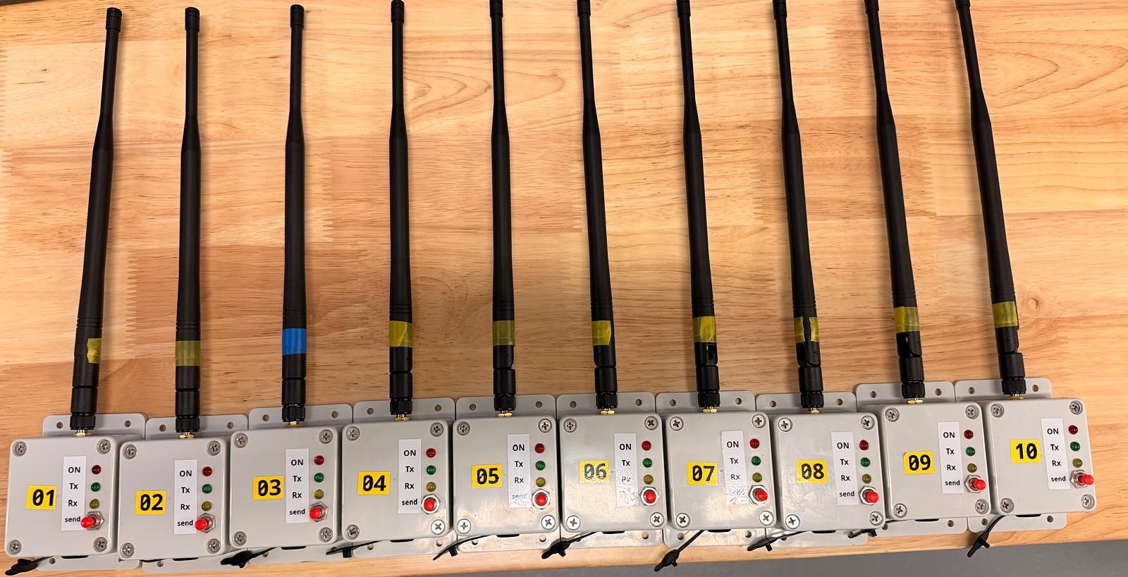
Main components on the 169 gateway
169 gateway bill of materials (BOM)
64 components, 25 distinct parts — part numbers from the project's BOM.
| Qty | Part | Footprint | Refs |
|---|---|---|---|
| 1 | TPS2553DDBVR TPS2553DDBVR_EDIT | SOT95P280X145-6N | IC2 |
| 1 | USBLC6-2SC6 | SOT-23-6 | U3 |
| 1 | CH340N | JEITA_SOIC-8_3.9x4.9mm_P1.27mm | U4 |
| 1 | BGS12P2L6E6327 | Infineon_PG-TSNP-6-10_0.7x1.1mm_0.7x1.1mm_P0.4mm | U5 |
| 1 | MCP1700X-330XXTT MCP1700x-330xxTT | SOT-23 | U6 |
| 1 | ATMEGA328P-M ATmega328P-M | QFN-32-1EP_5x5mm_P0.5mm_EP3.1x3.1mm | U7 |
| 1 | C341524 Resonator | Resonator_SMD_Murata_CSTxExxV-3Pin_3.0x1.1mm | Y1 |
| 1 | USB_C_RECEPTACLE_USB2.0_16P USB_C_Receptacle_USB2.0_16P | USB_C_Receptacle_XKB_U262-16XN-4BVC11 | J1 |
| 1 | LFCN-190 | Filter_Mini-Circuits_FV1206 | FL1 |
| 2 | C527608 FerriteBead | L_1206_3216Metric | FB1, FB2 |
| 2 | 180NH 180nH | L_0603_1608Metric | L1, L2 |
| 1 | 10U 10u | L_0603_1608Metric | L3 |
| 2 | 100U 100u | CP_EIA-6032-28_Kemet-C | C1, C2 |
| 3 | 10U 10u | C_0805_2012Metric | C3, C4, C21 |
| 4 | 1u | C_0603_1608Metric | C5, C6, C16, C17 |
| 13 | 100N 100n | C_0603_1608Metric | C7, C8, C9, C10, C11, C14, C15, C18 +5 |
| 2 | 2.2P 2.2p | C_0603_1608Metric | C12, C13 |
| 4 | 470P 470p | C_0402_1005Metric | C25, C26, C27, C28 |
| 2 | 5.1K 5.1k | R_0603_1608Metric | R1, R2 |
| 6 | 22 | R_0402_1005Metric | R3, R4, R13, R14, R15, R20 |
Show 5 more
| Qty | Part | Footprint | Refs |
|---|---|---|---|
| 7 | 100K 100k | R_0402_1005Metric | R5, R7, R17, R18, R19, R21, R22 |
| 1 | 20K 20k | R_0402_1005Metric | R6 |
| 2 | 4K7 4k7 | R_0402_1005Metric | R8, R9 |
| 3 | 100 | C_0402_1005Metric | R10, R11, R12 |
| 1 | 10K 10k | R_0402_1005Metric | R16 |
169 gateway design files
The KiCad project lives in the vsb-fei-440/LoRa-169 repository on GitHub; these links point at the commit this page was built from.
169 gateway: common questions
What microcontroller does the 169 gateway use?
The 169 gateway is built around the ATMEGA328P-M, from the AVR/Arduino family.
How big is the 169 gateway PCB?
The 169 gateway measures 65 × 75 mm, has 4 copper layers and is 1.6 mm thick.
How many components are on the 169 gateway?
64 components, from 25 distinct parts, with part numbers taken from the project's own BOM. The full bill of materials is listed on this page.
Where can I download the 169 gateway design files?
From the vsb-fei-440/LoRa-169 repository on GitHub, which has the KiCad layout, the schematic and the BOM; the links under Design files point to each one.
Can I use the 169 gateway design in my own project?
Yes, under the terms of its MIT license, which vsb-fei-440 chose for the repository.
Can I test firmware for the 169 gateway without the hardware?
Yes. HardLabs builds a simulation of the board from its netlist and BOM, so you can run and debug AVR/Arduino firmware against it before you order a PCB.
More boards in LoRa-169
Similar boards
 AVR/Arduino
Magspoof
samyk
35 × 29 mm11 parts2LNo license4.2k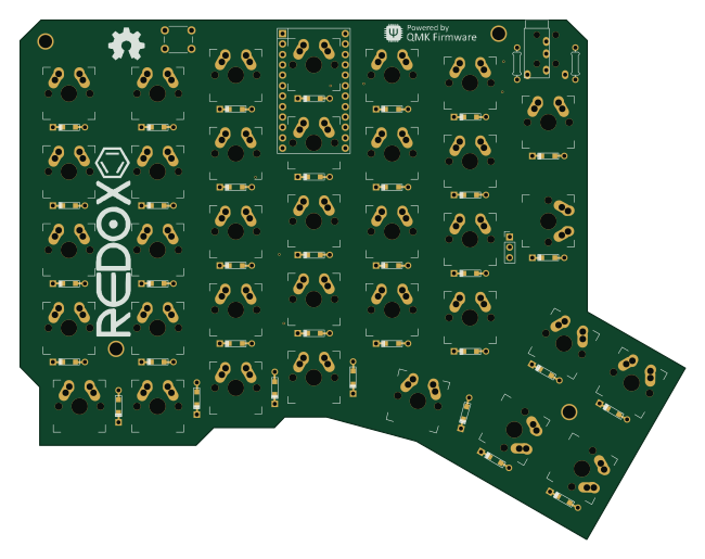 AVR/Arduino
Redox keyboard
mattdibi
162.2 × 126.5 mm77 parts2LMIT2.0k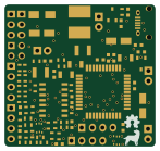 AVR/Arduino
Labrador
espotek-org
36.8 × 34.7 mm75 parts2LNo license1.2k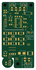 AVR/Arduino
ModuleV450
stuartpittaway
30 × 61.4 mm39 parts2LCC-BY-NC-4.01.1k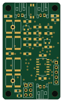 AVR/Arduino
V4
30 × 50 mm38 parts2LCC-BY-NC-4.01.1k AVR/Arduino
Discipline
coseyfannitutti
304.9 × 122.8 mm170 parts2LCC-BY-NC-4.01.0k