
Analog ai chip

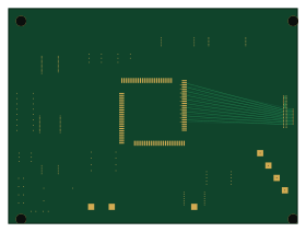
About the Analog ai chip PCB
Analog ai chip is an open source STM32 PCB design by vyquocvu, published on GitHub under the MIT license. It is a 4-layer board measuring 70 × 52 mm, with 21 components from 18 distinct parts.
Its main chip is the STM32U575VGT6, from the STM32 family. Other key parts include the BQ25120AYFPR, W25Q128JVSIQ, TCA8418RTWR, DRV2605LDGSR and TPS61099DRVR. By type, the board carries 8 ICs, 6 connectors, 6 resistors and 1 diode.
It belongs with the displays & leds and power & battery designs in this gallery.
From the project
This directory contains the editable KiCad 10 source for the 70 mm × 52 mm, four-layer Pager-1 main carrier. The display, keypad, protected Li-Po pack, and analog accelerator are external assemblies.
This directory contains the editable KiCad 10 source for the 70 mm × 52 mm, four-layer Pager-1 main carrier. The display, keypad, protected Li-Po pack, and analog accelerator are external assemblies.
Status: INCOMPLETECARRIERDESIGN. Do not fabricate this placeholder as a working product. Subsystem sheets contain text only, most components are unconnected, and generated footprints do not implement the declared packages. The BOM lacks the PMIC inductor and capacitors. Clean ERC/DRC on passive, no-connect symbols does not establish electrical completeness.
Main components on the Analog ai chip
Analog ai chip bill of materials (BOM)
21 components, 18 distinct parts — part numbers from the project's BOM.
| Qty | Part | Footprint | Refs |
|---|---|---|---|
| 1 | STM32U575VGT6 STMicroelectronics | STM32U575VGT6 | U1 |
| 1 | BQ25120AYFPR BQ25120A Texas Instruments | BQ25120A | U2 |
| 1 | W25Q128JVSIQ W25Q128JVS Winbond | W25Q128JVS | U3 |
| 1 | TCA8418RTWR TCA8418 Texas Instruments | TCA8418 | U4 |
| 1 | DRV2605LDGSR DRV2605L Texas Instruments | DRV2605L | U5 |
| 1 | TPS61099DRVR TPS61099 Texas Instruments | TPS61099 | U6 |
| 1 | TLV75510PDBVR TLV75510 Texas Instruments | TLV75510 | U7 |
| 1 | SN74AHCT125PWR SN74AHCT125 Texas Instruments | SN74AHCT125 | U8 |
| 1 | USB4105-GF-A USB_C_USB2.0 GCT | USB_C_USB2.0 | J1 |
| 1 | FH12-10S-0.5SH(55) LS027B7DH01_FPC Hirose | LS027B7DH01_FPC | J2 |
| 1 | FH12-12S-0.5SH(55) KEYPAD_5X7_FPC Hirose | KEYPAD_5X7_FPC | J3 |
| 1 | FTSH-105-01-L-DV-K SWD Samtec | SWD | J4 |
| 1 | DF40C-40DP-0.4V(51) DF40C-40DP-0.4V Hirose | DF40C-40DP-0.4V | J5 |
| 1 | S3B-PH-K-S LIPO_NTC JST | LIPO_NTC | J6 |
| 1 | USBLC6-2SC6 STMicroelectronics | USBLC6-2SC6 | D1 |
| 2 | RC0402FR-075K1L 5.1k Yageo | 5.1k | R1, R2 |
| 1 | RC0402FR-072KL 2.0k Yageo | 2.0k | R3 |
| 3 | RC0402FR-07100KL 100k Yageo | 100k | R4, R5, R6 |
Analog ai chip design files
The KiCad project lives in the vyquocvu/analog-ai-chip repository on GitHub; these links point at the commit this page was built from.
Analog ai chip: common questions
What microcontroller does the Analog ai chip use?
The Analog ai chip is built around the STM32U575VGT6, from the STM32 family.
How big is the Analog ai chip PCB?
The Analog ai chip measures 70 × 52 mm, has 4 copper layers and is 1.2 mm thick.
How many components are on the Analog ai chip?
21 components, from 18 distinct parts, with part numbers taken from the project's own BOM. The full bill of materials is listed on this page.
Where can I download the Analog ai chip design files?
From the vyquocvu/analog-ai-chip repository on GitHub, which has the KiCad layout, the schematic and the BOM; the links under Design files point to each one.
Can I use the Analog ai chip design in my own project?
Yes, under the terms of its MIT license, which vyquocvu chose for the repository.
Can I test firmware for the Analog ai chip without the hardware?
Yes. HardLabs builds a simulation of the board from its netlist and BOM, so you can run and debug STM32 firmware against it before you order a PCB.
Similar boards
 STM32
STM32AxxSolder
AxxAxx
39 × 82.5 mm122 parts2LGPL-3.01.7k STM32
STM32AIOC
skuep
21 × 31.5 mm47 parts2LMIT1.4k STM32
STM32Ferris
pierrechevalier83
208.8 × 86.8 mm102 parts2LSHL-2.11.3k STM32
STM32Module 16S
stuartpittaway
71.1 × 89.6 mm113 parts4LCC-BY-NC-4.01.1k STM32
STM32Djinn
tzarc
192.3 × 150.5 mm216 parts2LCERN-OHL-S-2.0988 STM32
STM32Ghoul
228.6 × 79.4 mm163 parts2LCERN-OHL-S-2.0988