
Red ducky

About the Red ducky PCB
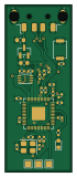
Red ducky is an open source RP2040/RP2350 PCB design by Xpandaru, published on GitHub. It is a 2-layer board measuring 16 × 40 mm, with 30 components from 14 distinct parts.
Its main chip is the RP2040, from the RP2040/RP2350 family. Other key parts include the MCP1700X-330XXTT and C2843335. By type, the board carries 17 capacitors, 6 resistors, 3 ICs, 1 crystal, 1 connector and 1 switch.
It belongs with the keyboards designs in this gallery.
From the project
In this project I'll make my own Rubber Ducky, named Red ducky ! A Rubber Ducky is a hacking tool that mimics a keyboard to inject a sequence of keys. I started this project with no knowledge of PCB design, so it promises to be very educational.
It all started when a friend introduced me to Hack Club during the Cyber Ninja CTF (a cybersecurity competition organized by Oteria Cyber School). I was quickly drawn to the Blueprint program because I knew absolutely nothing about electronics, and being very curious, I saw it as the perfect opportunity to explore the field. I soon had the idea to recreate a Rubber Ducky (a very popular cybersecurity tool) to understand how it worked and have my own by the end of the project. From there, I began learning all the necessary knowledge and developing my project based on the custom devboard…
Main components on the Red ducky
Red ducky bill of materials (BOM)
30 components, 14 distinct parts — part numbers from the project's BOM.
| Qty | Part | Footprint | Refs |
|---|---|---|---|
| 1 | RP2040 | QFN-56-1EP_7x7mm_P0.4mm_EP3.2x3.2mm | U1 |
| 1 | MCP1700X-330XXTT MCP1700x-330xxTT | SOT-23 | U2 |
| 1 | C2843335 W25Q16JVUXIQ TR | Winbond_USON-8-1EP_3x2mm_P0.5mm_EP0.2x1.6mm | U3 |
| 1 | C93234 12 MHz | Crystal_SMD_3225-4Pin_3.2x2.5mm | Y1 |
| 1 | C2765195 USB_A | USB_A_Molex_48037-2200_Horizontal | J1 |
| 1 | SW_Push | SW_Push_SPST_NO_Alps_SKRK | SW1 |
| 1 | LED | LED_0603_1608Metric | D1 |
| 2 | 1UF 1uF | C_0402_1005Metric | C1, C10 |
| 11 | 0.1UF 0.1uF | C_0402_1005Metric | C2, C3, C4, C5, C6, C7, C8, C9 +3 |
| 2 | 10UF 10uF | C_0603_1608Metric | C13, C14 |
| 2 | 33PF 33pF | C_0402_1005Metric | C15, C16 |
| 2 | 22 | R_0402_1005Metric | R1, R2 |
| 3 | 1K | R_0402_1005Metric | R3, R5, R6 |
| 1 | 10K | R_0402_1005Metric | R4 |
Red ducky design files
The KiCad project lives in the Xpandaru/Red-ducky repository on GitHub; these links point at the commit this page was built from.
- LayoutPCB/red_ducky.kicad_pcb
- SchematicPCB/red_ducky.kicad_sch
- BOMPCB/PRODUCTION/BOM.csv
Red ducky: common questions
What microcontroller does the Red ducky use?
The Red ducky is built around the RP2040, from the RP2040/RP2350 family.
How big is the Red ducky PCB?
The Red ducky measures 16 × 40 mm, has 2 copper layers and is 1.6 mm thick.
How many components are on the Red ducky?
30 components, from 14 distinct parts, with part numbers taken from the project's own BOM. The full bill of materials is listed on this page.
Where can I download the Red ducky design files?
From the Xpandaru/Red-ducky repository on GitHub, which has the KiCad layout, the schematic and the BOM; the links under Design files point to each one.
Can I use the Red ducky design in my own project?
The repository has no license, so all rights stay with Xpandaru. Use it as a reference, and ask the author before reusing the design.
Can I test firmware for the Red ducky without the hardware?
Yes. HardLabs builds a simulation of the board from its netlist and BOM, so you can run and debug RP2040/RP2350 firmware against it before you order a PCB.
Similar boards
 RP2040/RP2350
Open Book Abridged Edition
joeycastillo
85 × 115 mm29 parts2LCC-BY-SA-4.08.1k RP2040/RP2350
Corne
foostan
277.2 × 107.5 mm164 parts2LCC-BY-4.07.7k RP2040/RP2350
Corne
277.2 × 107.5 mm164 parts2LCC-BY-4.07.7k RP2040/RP2350
LogicAnalyzer
gusmanb
57 × 55.2 mm6 parts2LGPL-3.05.0k RP2040/RP2350
Jitx design
55.5 × 65 mm26 parts4LGPL-3.05.0k RP2040/RP2350
Pro V2
kata0510
290.1 × 130 mm270 parts2LMIT2.3k