
Logic board

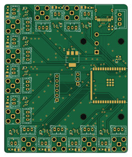
About the Logic board
Logic board is an open source ESP32 PCB design by zhangyuyi99, published on GitHub. It is a 2-layer board measuring 65.3 × 78.6 mm, with 114 components from 18 distinct parts.
Its main chip is the ESP32-S3-WROOM-1, from the ESP32 family. Other key parts include the AMS1117-3.3. By type, the board carries 34 connectors, 24 resistors, 21 diodes, 20 jumpers, 12 capacitors and 2 ICs.
It belongs with the iot & wireless designs in this gallery.
From the project
A hot wire anemometer based on ESP32
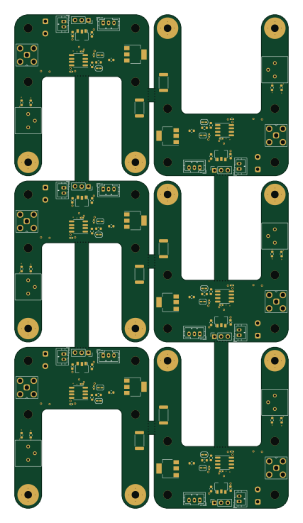
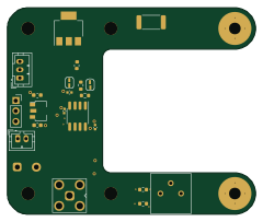
This project includes the design and implementation of a Wi-Fi enabled anemometer. The anemometer consists of a hardware portion which includes the PCB designs for the main board and logic board and a software portion which includes the firmware for operating the anemometer. The anemometer uses a hot wire method for wind speed measurement, and it includes a function to monitor battery voltage, disabling wind readings when the voltage drops below 7V until it recovers.
Main components on the Logic board
Logic board bill of materials (BOM)
114 components, 18 distinct parts — part numbers from the project's BOM.
| Qty | Part | Footprint | Refs |
|---|---|---|---|
| 1 | ESP32-S3-WROOM-1 | ESP32-S3-WROOM-1 | U1 |
| 1 | AMS1117-3.3 | SOT-223-3_TabPin2 | U2 |
| 1 | C5116482 DIRECT_HEADER | PinHeader_1x03_P2.54mm_Vertical | J1 |
| 1 | C5224026 ESPFLASH | PinSocket_1x06_P2.54mm_Vertical | J2 |
| 1 | CONN_01X03_FEMALE Conn_01x03_Female | JST_XH_B3B-XH-A_1x03_P2.50mm_Vertical | J3 |
| 1 | USB_C_RECEPTACLE_USB2.0 USB_C_Receptacle_USB2.0 | USB_C_Receptacle_HRO_TYPE-C-31-M-12 | J4 |
| 10 | CONN_01X03 Conn_01x03 | JST_PH_B3B-PH-K_1x03_P2.00mm_Vertical | J5, J6, J7, J8, J9, J10, J11, J12 +2 |
| 10 | C411575 SMA | SMA_Amphenol_901-143_Horizontal | J15, J16, J17, J18, J19, J20, J21, J22 +2 |
| 10 | C131337 JST | JST_PH_B2B-PH-K_1x02_P2.00mm_Vertical | J25, J26, J27, J28, J29, J30, J31, J32 +2 |
| 10 | FILTER_BYPASS | SolderJumper-2_P1.3mm_Open_RoundedPad1.0x1.5mm | JP1, JP2, JP3, JP4, JP5, JP6, JP7, JP8 +2 |
| 10 | V_CLAMP | SolderJumper-2_P1.3mm_Bridged2Bar_RoundedPad1.0x1.5mm | JP11, JP12, JP13, JP14, JP15, JP16, JP17, JP18 +2 |
| 1 | C319012 SW_SPDT | switch_4.7mm | SW1 |
| 11 | 3.3V | D_SOD-523 | D1, D12, D13, D14, D15, D16, D17, D18 +3 |
| 10 | LED | LED_0805_2012Metric | D2, D3, D4, D5, D6, D7, D8, D9 +2 |
| 12 | 1UF 1uF | C_0402_1005Metric | C2, C4, C5, C6, C7, C8, C9, C10 +4 |
| 1 | 10K 10k | R_0402_1005Metric | R1 |
| 13 | 5.1K 5.1k | R_0603_1608Metric | R2, R3, R4, R5, R7, R9, R11, R13 +5 |
| 10 | 1k | R_0402_1005Metric | R6, R8, R10, R12, R14, R16, R18, R20 +2 |
Logic board design files
The KiCad project lives in the zhangyuyi99/hot-wire-anemometer repository on GitHub; these links point at the commit this page was built from.
Logic board: common questions
What microcontroller does the Logic board use?
The Logic board is built around the ESP32-S3-WROOM-1, from the ESP32 family.
How big is the Logic board?
The Logic board measures 65.3 × 78.6 mm, has 2 copper layers and is 1.6 mm thick.
How many components are on the Logic board?
114 components, from 18 distinct parts, with part numbers taken from the project's own BOM. The full bill of materials is listed on this page.
Where can I download the Logic board design files?
From the zhangyuyi99/hot-wire-anemometer repository on GitHub, which has the KiCad layout, the schematic and the BOM; the links under Design files point to each one.
Can I use the Logic board design in my own project?
The repository has no license, so all rights stay with zhangyuyi99. Use it as a reference, and ask the author before reusing the design.
Can I test firmware for the Logic board without the hardware?
Yes. HardLabs builds a simulation of the board from its netlist and BOM, so you can run and debug ESP32 firmware against it before you order a PCB.
More boards in hot-wire-anemometer
Similar boards
 ESP32
OSO-BOOK-B1
joeycastillo
85 × 115 mm65 parts2LCC-BY-SA-4.08.1k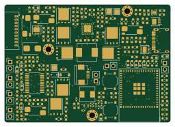 ESP32
Powertrain
byrantech
64 × 45.4 mm171 parts4LMIT4.3k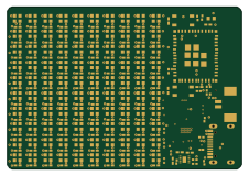 ESP32
Badge
atopile
56.3 × 39 mm239 parts4LMIT4.0k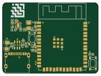 ESP32
Esp32 minimal
36.2 × 26.8 mm20 parts2LMIT4.0k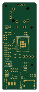 ESP32
Controller
StuckAtPrototype
29 × 74 mm58 parts4LApache-2.03.8k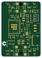 ESP32
Racer
36 × 50.2 mm70 parts4LApache-2.03.8k