
Autonomous mower

About the Autonomous mower PCB
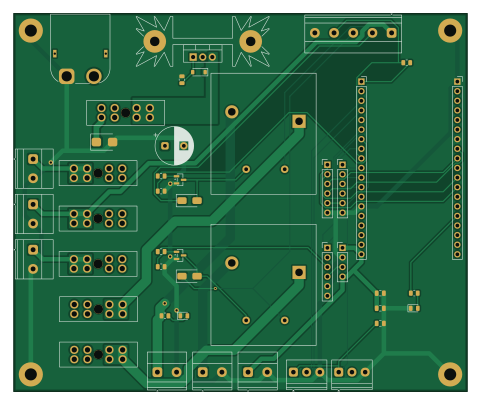
Autonomous mower is an open source ESP32 PCB design by zohebzma2-cmyk, published on GitHub under the MIT license. It is a 2-layer board measuring 120 × 100 mm, with 46 components from 39 distinct parts.
Its main chip is the ESP32 DevKitC J2, from the ESP32 family. By type, the board carries 8 resistors, 6 fuses, 5 connectors, 4 diodes, 4 capacitors and 3 transistors.
It belongs with the robotics & motion, rf & radio and retro computing designs in this gallery.
From the project
Self-driving zero-turn mower retrofit — RTK GPS, LiDAR, cameras, on-device AI. Hardware + firmware + control software + parametric CAD.
Power input + reverse-polarity protection + 30 A main fuse + five fused branches, the hardware kill chain (E-stop NC contacts in series with FET-switched relay coils), and the ESP32-DevKitC carrier for the lap-bar controller. 120 × 100 mm, 2 layers, 2 oz copper.
The .kicad files are generated. Edit design.py (parts + nets) or genpcb.py (placement, pours, routing), then regenerate** — don't hand-edit the outputs, they'd be overwritten.
Autonomous mower bill of materials (BOM)
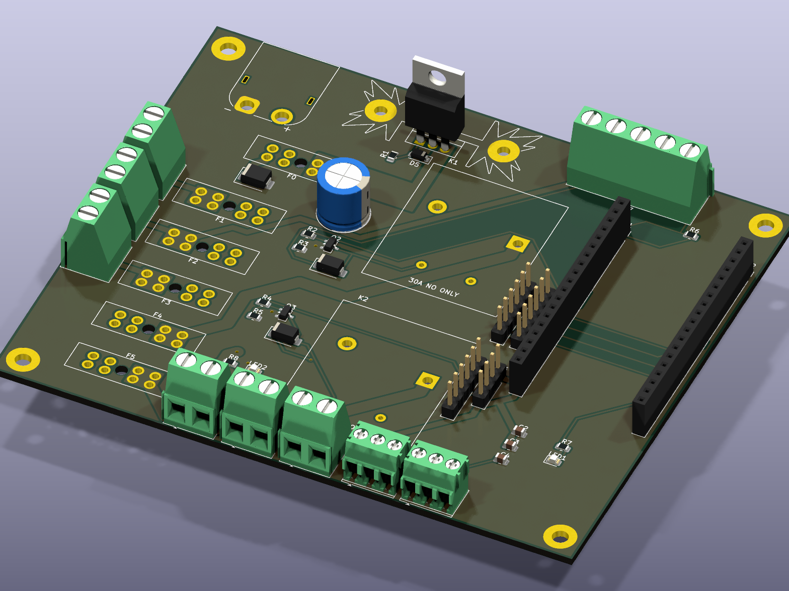
46 components, 39 distinct parts — part numbers from the project's BOM.
| Qty | Part | Footprint | Refs |
|---|---|---|---|
| 1 | IRF4905 | TO-220-3_Vertical | Q1 |
| 2 | AO3400A | SOT-23 | Q2, Q3 |
| 1 | XT60PW-M 12V IN | AMASS_XT60PW-M_1x02_P7.20mm_Horizontal | J1 |
| 1 | J_FC: Pixhawk SERVO1/3/6/5 | PinHeader_1x06_P2.54mm_Vertical | J2 |
| 1 | J_5V: servo + ultrasonic | PinHeader_1x04_P2.54mm_Vertical | J3 |
| 1 | J_M1: IBT-2 #1 (left) | PinHeader_1x06_P2.54mm_Vertical | J4 |
| 1 | J_M2: IBT-2 #2 (right) | PinHeader_1x06_P2.54mm_Vertical | J5 |
| 1 | 20A ATO (main) | FuseHolder_Blade_ATO_Littelfuse_FLR_178.6165 | F0 |
| 1 | 5A ATO (Pi buck) | FuseHolder_Blade_ATO_Littelfuse_FLR_178.6165 | F1 |
| 1 | 3A ATO (logic buck, e-stop) | FuseHolder_Blade_ATO_Littelfuse_FLR_178.6165 | F2 |
| 1 | 2A ATO (PM02) | FuseHolder_Blade_ATO_Littelfuse_FLR_178.6165 | F3 |
| 1 | 10A ATO (drive) | FuseHolder_Blade_ATO_Littelfuse_FLR_178.6165 | F4 |
| 1 | 7.5A ATO (PTO) | FuseHolder_Blade_ATO_Littelfuse_FLR_178.6165 | F5 |
| 1 | ESP32 DevKitC J2 | PinSocket_1x19_P2.54mm_Vertical | H1 |
| 1 | ESP32 DevKitC J3 | PinSocket_1x19_P2.54mm_Vertical | H2 |
| 1 | SK 104 50,8 STC 9K/W | Heatsink_Fischer_SK104-STC-STIC_35x13mm_2xDrill2.5mm | HS1 |
| 1 | SLA-12VDC-SL-A DRIVE | Relay_SPST_Songle_SLA-xxVDC-SL-A | K1 |
| 1 | SLA-12VDC-SL-A PTO | Relay_SPST_Songle_SLA-xxVDC-SL-A | K2 |
| 1 | BUCK1 (Pi 5) | TerminalBlock_Phoenix_MKDS-1,5-2-5.08_1x02_P5.08mm_Horizontal | TB1 |
| 1 | BUCK2 (logic) | TerminalBlock_Phoenix_MKDS-1,5-2-5.08_1x02_P5.08mm_Horizontal | TB2 |
Show 19 more
| Qty | Part | Footprint | Refs |
|---|---|---|---|
| 1 | PM02 (Pixhawk) | TerminalBlock_Phoenix_MKDS-1,5-2-5.08_1x02_P5.08mm_Horizontal | TB3 |
| 1 | MOTOR V+ (IBT-2 B+) | TerminalBlock_Phoenix_MKDS-1,5-2-5.08_1x02_P5.08mm_Horizontal | TB4 |
| 1 | PTO clutch | TerminalBlock_Phoenix_MKDS-1,5-2-5.08_1x02_P5.08mm_Horizontal | TB5 |
| 1 | 5V IN (buck #2) | TerminalBlock_Phoenix_MKDS-1,5-2-5.08_1x02_P5.08mm_Horizontal | TB6 |
| 1 | TB_ESTOP: 12V,NC1,NC2,SIG,GND | TerminalBlock_Phoenix_MKDS-1,5-5-5.08_1x05_P5.08mm_Horizontal | TB7 |
| 1 | TB_POT_L: 3V3,wiper,GND | TerminalBlock_Phoenix_PT-1,5-3-3.5-H_1x03_P3.50mm_Horizontal | TB8 |
| 1 | TB_POT_R: 3V3,wiper,GND | TerminalBlock_Phoenix_PT-1,5-3-3.5-H_1x03_P3.50mm_Horizontal | TB9 |
| 1 | green: STATUS | LED_0805_2012Metric | LED1 |
| 1 | red: DRIVE LIVE | LED_0805_2012Metric | LED2 |
| 1 | SMBJ16A TVS | D_SMB | D1 |
| 2 | SS34 flyback | D_SMA | D2, D3 |
| 1 | BZT52C15 (15V) | D_SOD-123 | D5 |
| 1 | 470u 25V | CP_Radial_D10.0mm_P5.00mm | C1 |
| 2 | 100N 100n | C_0805_2012Metric | C2, C4 |
| 1 | 10u 25V | C_0805_2012Metric | C3 |
| 4 | 10K 10k | R_0805_2012Metric | R1, R3, R5, R6 |
| 2 | 100 | R_0805_2012Metric | R2, R4 |
| 1 | 220 | R_0805_2012Metric | R7 |
| 1 | 2k | R_0805_2012Metric | R8 |
Autonomous mower design files
The KiCad project lives in the zohebzma2-cmyk/autonomous-mower repository on GitHub; these links point at the commit this page was built from.
Autonomous mower: common questions
What microcontroller does the Autonomous mower use?
The Autonomous mower is built around the ESP32 DevKitC J2, from the ESP32 family.
How big is the Autonomous mower PCB?
The Autonomous mower measures 120 × 100 mm, has 2 copper layers and is 1.6 mm thick.
How many components are on the Autonomous mower?
46 components, from 39 distinct parts, with part numbers taken from the project's own BOM. The full bill of materials is listed on this page.
Where can I download the Autonomous mower design files?
From the zohebzma2-cmyk/autonomous-mower repository on GitHub, which has the KiCad layout, the schematic and the BOM; the links under Design files point to each one.
Can I use the Autonomous mower design in my own project?
Yes, under the terms of its MIT license, which zohebzma2-cmyk chose for the repository.
Can I test firmware for the Autonomous mower without the hardware?
Yes. HardLabs builds a simulation of the board from its netlist and BOM, so you can run and debug ESP32 firmware against it before you order a PCB.
Similar boards
 ESP32
ESP32Open Book Abridged Edition
joeycastillo
85 × 115 mm65 parts2LCC-BY-SA-4.08.1k ESP32
ESP32Badge
atopile
56.3 × 39 mm239 parts4LMIT4.0k ESP32
ESP32Esp32 minimal
36.2 × 26.8 mm20 parts2LMIT4.0k ESP32
ESP32Racer
StuckAtPrototype
36 × 50.2 mm70 parts4LApache-2.03.8k ESP32
ESP32Controller
29 × 74 mm58 parts4LApache-2.03.8k ESP32
ESP32Bitaxe
skot
56.5 × 99.8 mm86 parts4LCERN-OHL-S-2.01.4k