
Mgc

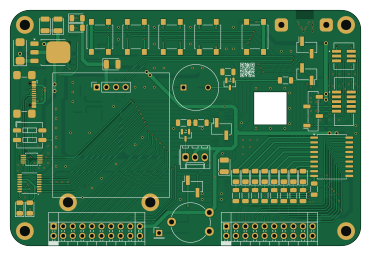
About the Mgc PCB
Mgc is an open source PCB design by 0x007E, published on GitHub under the CC-BY-NC-4.0 license. It is a 2-layer board measuring 92.7 × 62.2 mm, with 108 components from 44 distinct parts.
Other key parts include the FT230XS, TS3USB30EDGSR, 74AHC1G14, TPS2116DRL and LM1117DT-3.3. By type, the board carries 37 resistors, 20 connectors, 15 diodes, 14 capacitors, 7 ICs and 6 switches.
From the project
MeGARCard - Development Platform
The MGC is built as base development board with a set of push-buttons, leds, potentiometers and many more components on-board. It builds the base platform for a bunchset of adaptable microcontrolles (e.g. ATmega16A, ATmega4808, ESP32). It simplifies the development process by extending supported microcontrollers to a range of actuators and sensors. The board itself regulates the voltage to 5V or 3V3 automatically with a power mux (TPS2116). If 3V3 and 5V are suppored, the voltage can be changed on the dip switch of the adaptable microcontroller board. The base board supports a usb or…

Main components on the Mgc
Mgc bill of materials (BOM)
108 components, 44 distinct parts.
| Qty | Part | Footprint | Refs |
|---|---|---|---|
| 1 | FT230XS | SSOP-16_3.9x4.9mm_P0.635mm | U1 |
| 1 | TS3USB30EDGSR | VSSOP-10_3x3mm_P0.5mm | U2 |
| 1 | 74AHC1G14 | SOT-23-5 | U3 |
| 1 | TPS2116DRL | SOT-583-8 | U4 |
| 1 | LM1117DT-3.3 | TO-252-3_TabPin2 | U5 |
| 1 | TBD62783A | SOIC-18W_7.5x11.6mm_P1.27mm | U6 |
| 1 | MB85RC04V | SOIC-8_3.9x4.9mm_P1.27mm | U7 |
| 5 | AO3416 | SOT-23 | Q9, Q10, Q11, Q12, Q13 |
| 1 | USB_C_Receptacle | USB_C_Receptacle_GCT_USB4110 | J1 |
| 4 | Conn_01x02_Pin | PinHeader_1x02_P2.54mm_Vertical_SMD_Pin1Right | J2, J18, J19, J20 |
| 5 | 103R012BB100 | AMPHENOL_103R012BB100 | J3, J7, J11, J12, J13 |
| 1 | Conn_02x03_Odd_Even | AMPHENOL_20021221-00006T4LF | J4 |
| 1 | Conn_02x05_Odd_Even | AMPHENOL_20021521-00010T4LF | J5 |
| 1 | Conn_01x04 | PinSocket_1x04_P2.54mm_Vertical | J6 |
| 2 | Conn_01x01_Pin | SolderWire-0.75sqmm_1x01_D1.25mm_OD3.5mm | J8, J9 |
| 1 | Conn_01x04_Pin | PinSocket_1x04_P2.54mm_Vertical_SMD_Pin1Right | J10 |
| 2 | Conn_02x10_Odd_Even | PinSocket_2x10_P2.54mm_Horizontal | J14, J15 |
| 1 | Conn_01x03 | Molex_KK-254_AE-6410-03A_1x03_P2.54mm_Vertical | J16 |
| 1 | Conn_01x01_Pin | PinHeader_1x01_P2.54mm_Vertical | J17 |
| 1 | Buzzer | MagneticBuzzer_ProSignal_ABT-410-RC | BZ1 |
Show 24 more
| Qty | Part | Footprint | Refs |
|---|---|---|---|
| 1 | 1A | Fuse_1206_3216Metric | F1 |
| 1 | 10k | Potentiometer_Piher_PT-10-V10_Vertical | RV1 |
| 5 | SW_SPST | SW_SPST_B3S-1000 | SW0, SW1, SW2, SW3, SW5 |
| 1 | SW_DIP_x02 | SW_DIP_SPSTx02_Slide_6.7x6.64mm_W6.73mm_P2.54mm_LowProfile_JPin | SW6 |
| 8 | Green | LED_1206_3216Metric | D0, D1, D2, D3, D4, D5, D10, D11 |
| 2 | Yellow | LED_1206_3216Metric | D6, D12 |
| 2 | Red | LED_1206_3216Metric | D7, D9 |
| 1 | B360A | D_SMA | D13 |
| 2 | BAT43 | D_MiniMELF | D14, D15 |
| 1 | 70Ω/100Mhz/3A | L_1206_3216Metric | FB1 |
| 7 | 100n | C_1206_3216Metric | C1, C4, C5, C6, C8, C12, C13 |
| 1 | 10n | C_0603_1608Metric | C2 |
| 4 | 100u | CP_EIA-3528-21_Kemet-B | C3, C7, C10, C11 |
| 1 | 47u | CP_EIA-6032-28_Kemet-C | C9 |
| 1 | n.B. | CP_EIA-3528-21_Kemet-B | C14 |
| 7 | 270 | R_1206_3216Metric | R1, R2, R3, R4, R5, R6, R38 |
| 3 | 330 | R_1206_3216Metric | R7, R8, R43 |
| 9 | 10k | R_1206_3216Metric | R9, R10, R31, R32, R34, R41, R45, R50 +1 |
| 7 | 3k3 | R_1206_3216Metric | R25, R26, R27, R28, R36, R37, R47 |
| 2 | 5k1 | R_1206_3216Metric | R29, R30 |
| 3 | 150 | R_1206_3216Metric | R33, R35, R39 |
| 2 | 1k | R_1206_3216Metric | R40, R42 |
| 3 | 47R | R_1206_3216Metric | R44, R48, R49 |
| 1 | 10R | R_1206_3216Metric | R46 |
Mgc design files
The KiCad project lives in the 0x007E/mgc repository on GitHub; these links point at the commit this page was built from.
- Layoutpcb/MGC.kicad_pcb
- Schematicpcb/MGC.kicad_sch
Mgc: common questions
How big is the Mgc PCB?
The Mgc measures 92.7 × 62.2 mm, has 2 copper layers and is 1.6 mm thick.
How many components are on the Mgc?
108 components, from 44 distinct parts. The full bill of materials is listed on this page.
Where can I download the Mgc design files?
From the 0x007E/mgc repository on GitHub, which has the KiCad layout and the schematic; the links under Design files point to each one.
Can I use the Mgc design in my own project?
It is published under CC-BY-NC-4.0, which limits how it may be reused; read the license before building on it.