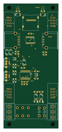
SDWire

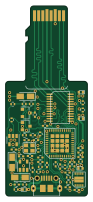
About the SDWire PCB
SDWire is an open source PCB design by 3mdeb, published on GitHub under the Apache-2.0 license. It is a 4-layer board measuring 21.6 × 50.4 mm, with 65 components from 28 distinct parts.
Other key parts include the USB2640-HZH-02, SPX3819M5, FT200XD, MC74HC1G04DTT1G and TS3A27518EPWR. By type, the board carries 26 capacitors, 16 resistors, 8 diodes, 6 ICs, 3 connectors and 3 inductors.
From the project
PCB Schematics for SDWire hardware
sd-mux stands for Secure Digital Multiplexer.
This is SD card switcher (multiplexer) designed to help automatic testing.
This project is sd-mux controller - binary for controlling sd-mux device.
Requirements: 1. libftdi1 1.4 - development library 2. popt - development library 3. cmake - binary tool
Build: - enter into project directory - create 'build' directory - enter into "build" directory - run 'cmake ..' - run 'make'
Main components on the SDWire
SDWire bill of materials (BOM)
65 components, 28 distinct parts.
| Qty | Part | Footprint | Refs |
|---|---|---|---|
| 1 | USB2640-HZH-02 | QFN-48-1EP_7x7mm_Pitch0.5mm | U1 |
| 1 | SPX3819M5 | SOT-23-5 | U2 |
| 1 | FT200XD | DFN-10-1EP_3x3mm_Pitch0.5mm | U3 |
| 1 | MC74HC1G04DTT1G | SOT-23-5 | U4 |
| 1 | TS3A27518EPWR | TSSOP-24 | U5 |
| 1 | AT24CS02-SSHM | SO-8_3.9x4.9mm_P1.27mm | U6 |
| 2 | MMBT4403LT1 | SOT-23 | Q3, Q4 |
| 1 | 24MHz | Crystal_SMD_2520-4pin_2.5x2.0mm | Y1 |
| 1 | usd-plug | usd | J1 |
| 1 | uSD Socket | microSD_HC_Wuerth_693072010801 | J2 |
| 1 | USB_OTG_MICRO_USB | micro_sub_molex | P1 |
| 2 | OSB50402C1E | LED_0402 | D1, D6 |
| 2 | RED | LED_0402 | D2, D5 |
| 2 | BLUE | LED_0402 | D3, D7 |
| 2 | GREEN | LED_0402 | D4, D8 |
| 3 | BLM15PD121SN1D | R_0402 | L1, L2, L3 |
| 15 | 100nF/16V | C_0402 | C1, C2, C6, C8, C9, C11, C12, C13 +7 |
| 2 | 33p/50V | C_0402 | C3, C4 |
| 4 | 1uF/16V | C_0402 | C5, C7, C19, C21 |
| 3 | 10uF/10V | CP_Tantalum_Case-A_EIA-3216-18_Reflow | C10, C14, C27 |
Show 8 more
| Qty | Part | Footprint | Refs |
|---|---|---|---|
| 2 | 47pF | C_0402 | C22, C23 |
| 4 | 10K | R_0402 | R1, R2, R9, R10 |
| 1 | 1M | R_0402 | R3 |
| 1 | 12k 1% | R_0402 | R4 |
| 1 | 330R | R_0402 | R5 |
| 2 | 27R | R_0402 | R6, R7 |
| 2 | 10K | R_0402_1005Metric | R8, R16 |
| 5 | 1K | R_0402 | R11, R12, R13, R14, R15 |
SDWire design files
The KiCad project lives in the 3mdeb/SDWire repository on GitHub; these links point at the commit this page was built from.
SDWire: common questions
How big is the SDWire PCB?
The SDWire measures 21.6 × 50.4 mm, has 4 copper layers and is 0.8 mm thick.
How many components are on the SDWire?
65 components, from 28 distinct parts. The full bill of materials is listed on this page.
Where can I download the SDWire design files?
From the 3mdeb/SDWire repository on GitHub, which has the KiCad layout; the links under Design files point to each one.
Can I use the SDWire design in my own project?
Yes, under the terms of its Apache-2.0 license, which 3mdeb chose for the repository.