
Autotracking Surgical Lamp

About the Autotracking Surgical Lamp PCB
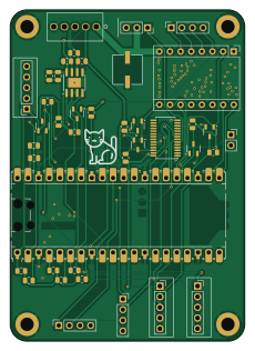
Autotracking Surgical Lamp is an open source RP2040/RP2350 PCB design by aeventre, published on GitHub. It is a 2-layer board measuring 56 × 79 mm, with 41 components from 20 distinct parts.
Its main chip is the 2648-SC0915, from the RP2040/RP2350 family. Other key parts include the MAX485E, PCA9685PW and POLOLU_BREAKOUT_DRV8825. By type, the board carries 17 resistors, 9 connectors, 6 transistors, 5 capacitors, 3 ICs and 1 module.
It belongs with the robotics & motion and sensors designs in this gallery.
From the project
This ROS 2 workspace contains all packages required for the Auto-Tracking Surgical Lamp system. The lamp uses 3D pose tracking of a handheld remote (via green ball detection) to plan and execute motions in real-time, with fallback modes for manual GUI control and demo sequences.
This ROS 2 workspace contains all packages required for the Auto-Tracking Surgical Lamp system. The lamp uses 3D pose tracking of a handheld remote (via green ball detection) to plan and execute motions in real-time, with fallback modes for manual GUI control and demo sequences. The system is built using ROS 2 Jazzy and MoveIt 2.
Manages the system's behavior based on user input. It switches between modes such as idle, manual control, tracking, zeroing, and demo.
Main components on the Autotracking Surgical Lamp
Autotracking Surgical Lamp bill of materials (BOM)
41 components, 20 distinct parts — part numbers from the project's BOM.
| Qty | Part | Footprint | Refs |
|---|---|---|---|
| 1 | 2648-SC0915 RaspberryPi_Pico | RaspberryPi_Pico_Common_Unspecified | MCU1 |
| 1 | MAX485E | SOIC-8-1EP_3.9x4.9mm_P1.27mm_EP2.29x3mm | U1 |
| 1 | PCA9685PW | TSSOP-28_4.4x9.7mm_P0.65mm | U2 |
| 1 | POLOLU_BREAKOUT_DRV8825 TMC2209 Stepper Driver | Pololu_Breakout-16_15.2x20.3mm | A1 |
| 6 | BSS138 | SOT-23-3 | Q1, Q2, Q3, Q4, Q5, Q6 |
| 1 | OSTVN05A150 joint2 | PinSocket_1x03_P2.54mm_Vertical | J1 |
| 1 | joint3 | PinSocket_1x04_P2.54mm_Vertical | J2 |
| 1 | joint4 | PinSocket_1x04_P2.54mm_Vertical | J3 |
| 1 | Headlamp | PinSocket_1x05_P2.54mm_Vertical | J4 |
| 1 | JOINT2 Joint 1 Encoder | PinSocket_1x05_P2.54mm_Vertical | J5 |
| 1 | JOINT3 Joint 2 Encoder | PinSocket_1x05_P2.54mm_Vertical | J6 |
| 1 | JOINT4 OSTVN05A150 | CONN5_516x256_OST | J7 |
| 1 | Stepper | PinSocket_1x04_P2.54mm_Vertical | J8 |
| 1 | Fan | PinSocket_1x02_P2.54mm_Vertical | J9 |
| 2 | 10UF 10uF | C_0805_2012Metric | C1, C3 |
| 2 | 0.1UF 0.1uF | C_0805_2012Metric | C2, C4 |
| 1 | 47UF 47uF | CAP_6.3 X 5.8_PAN | C5 |
| 14 | 10K 10k | R_0805_2012Metric | R1, R2, R3, R4, R5, R6, R7, R8 +6 |
| 2 | 20K 20k | R_0805_2012Metric | R14, R15 |
| 1 | 10K 120 | R_0805_2012Metric | R16 |
Autotracking Surgical Lamp design files
The KiCad project lives in the aeventre/Autotracking_Surgical_Lamp repository on GitHub; these links point at the commit this page was built from.
Autotracking Surgical Lamp: common questions
What microcontroller does the Autotracking Surgical Lamp use?
The Autotracking Surgical Lamp is built around the 2648-SC0915, from the RP2040/RP2350 family.
How big is the Autotracking Surgical Lamp PCB?
The Autotracking Surgical Lamp measures 56 × 79 mm, has 2 copper layers and is 1.6 mm thick.
How many components are on the Autotracking Surgical Lamp?
41 components, from 20 distinct parts, with part numbers taken from the project's own BOM. The full bill of materials is listed on this page.
Where can I download the Autotracking Surgical Lamp design files?
From the aeventre/Autotracking_Surgical_Lamp repository on GitHub, which has the KiCad layout, the schematic and the BOM; the links under Design files point to each one.
Can I use the Autotracking Surgical Lamp design in my own project?
The repository has no license, so all rights stay with aeventre. Use it as a reference, and ask the author before reusing the design.
Can I test firmware for the Autotracking Surgical Lamp without the hardware?
Yes. HardLabs builds a simulation of the board from its netlist and BOM, so you can run and debug RP2040/RP2350 firmware against it before you order a PCB.
Similar boards
 RP2040/RP2350
Open Book Abridged Edition
joeycastillo
85 × 115 mm29 parts2LCC-BY-SA-4.08.1k RP2040/RP2350
Corne
foostan
277.2 × 107.5 mm164 parts2LCC-BY-4.07.7k RP2040/RP2350
Corne
277.2 × 107.5 mm164 parts2LCC-BY-4.07.7k RP2040/RP2350
Jitx design
gusmanb
55.5 × 65 mm26 parts4LGPL-3.05.0k RP2040/RP2350
LogicAnalyzer
57 × 55.2 mm6 parts2LGPL-3.05.0k RP2040/RP2350
Main
google
98 × 71 mm102 parts2LApache-2.02.9k