
88 open source boards using the PCA9685PW
Real designs built with the PCA9685PW, from public GitHub projects: a quick way to see how others power, decouple and connect it. Each board comes with its KiCad files, full parts list and a render — and you can simulate its firmware on HardLabs.
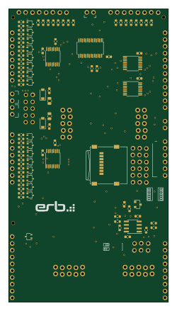
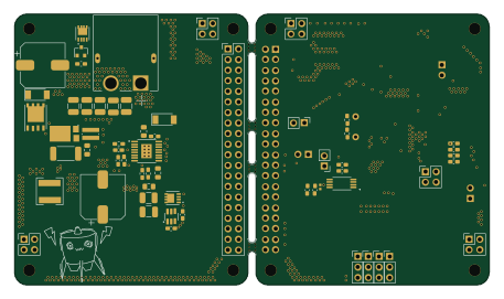
Kivu12
ohmtech-rdi
59.6 × 109.5 mm135 parts2LCC-BY-SA-4.0405- schematic only · 87 partsESP32
Antenny
RedBalloonShenanigans
87 partsNo license164 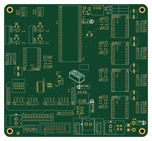
1 Distribution Board
basicallysource
130 × 120 mm179 parts2LNo license38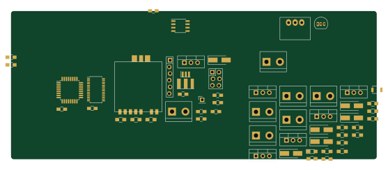 AVR/Arduino
HB-LC-Dim6PWM-CV
stan23
139 × 56.3 mm57 parts2LCC-BY-NC-4.021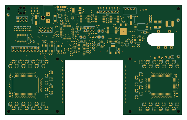 Microchip SAM
Purpledrop
uwmisl
161 × 100 mm253 parts4LMIT19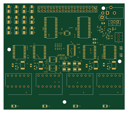
Eve pi
vishhvaan
103.5 × 90.6 mm102 parts4LMIT15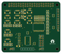
Reef piHat
Ranthalion
65 × 56 mm99 parts2LNo license13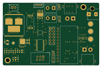
Robocar pinky
arkorobotics
81.3 × 52.8 mm83 parts4LNo license12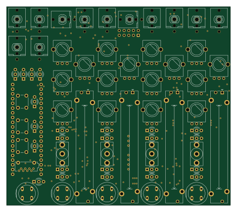
TapeLooper MainBoard
TheSlowGrowth
119.6 × 106.5 mm243 parts2LCustom license10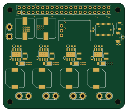
RPi-HAT-RGBW-LED-Controller
mikelawrence
65 × 56 mm54 parts2LMIT9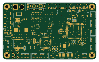
OpenJetECU
yuchao86
100.1 × 60.2 mm187 parts4LGPL-3.08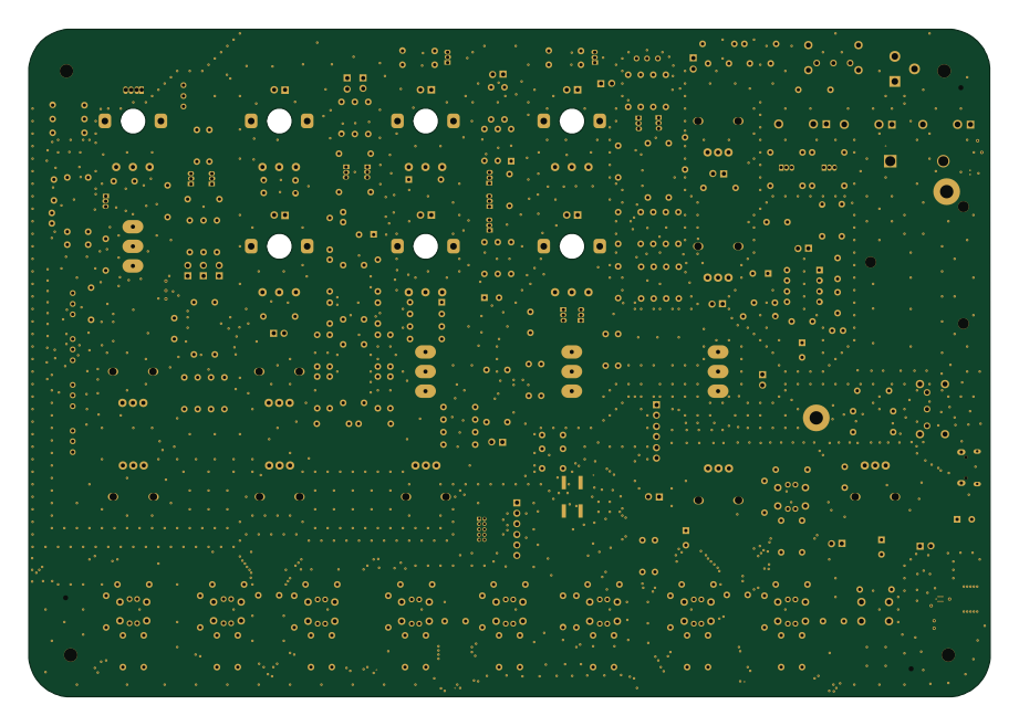 STM32
Liv Synth
SloBloLabs
230 × 159.9 mm273 parts2LMIT7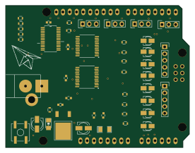 AVR/Arduino
Mcu
skiz
68.8 × 53.3 mm48 parts2LNo license4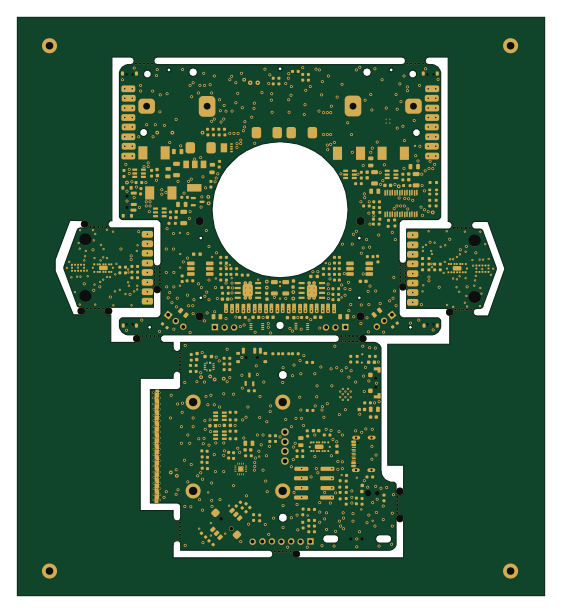 ESP32
Pannel
cocobot
139.5 × 153 mm266 parts2LNo license2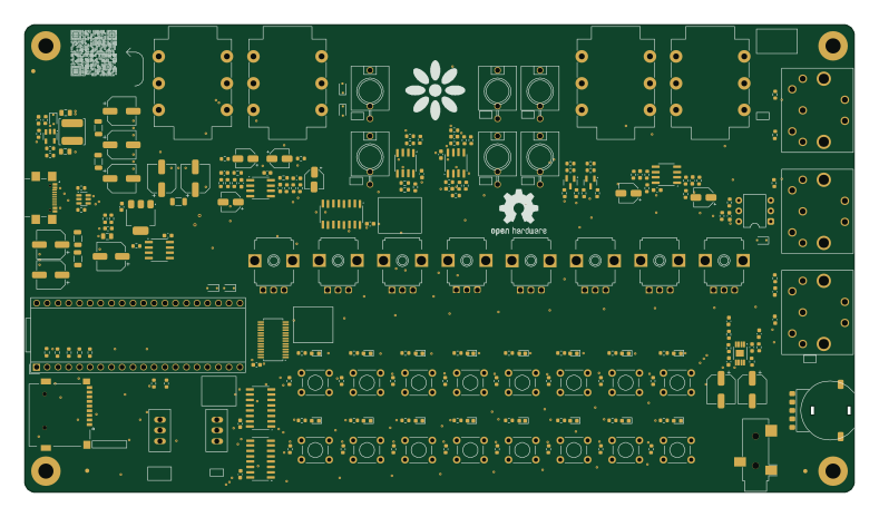
Seed3-DevKit-Desktop
daisyaudio
197 × 111 mm230 parts2LNo license2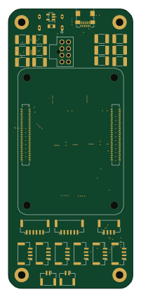 Raspberry Pi
CompactPi
loganrf
47 × 105 mm147 parts6LCERN-OHL-S-2.02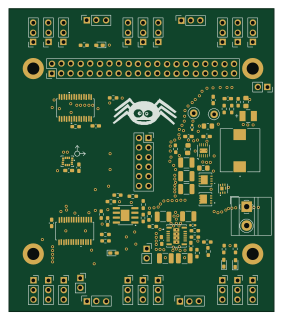
Self Balancing Hexapod Robot
aeventre
70 × 80 mm132 parts2LApache-2.02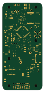 STM32
Ollyfc
rland93
45 × 98 mm101 parts4LMPL-2.02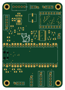 RP2040/RP2350
Autotracking Surgical Lamp
56 × 79 mm41 parts2LNo license2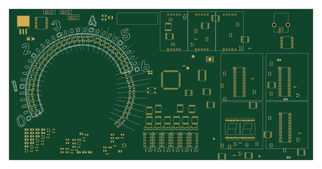 STM32
V1
Churrosoft
265.5 × 132.3 mm267 parts2LMIT1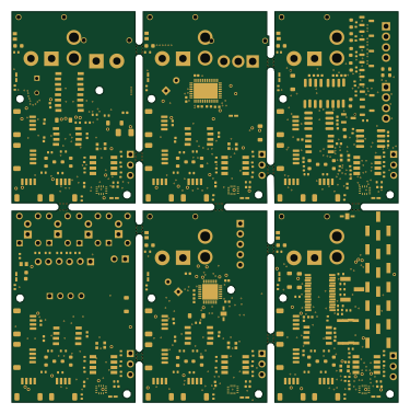
PaneledKit
williamthayer
93.6 × 94.4 mm226 parts2LNo license1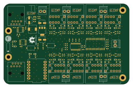 ESP32
LCCTurnoutController
vsi5004
116 × 74.5 mm170 parts2LNo license1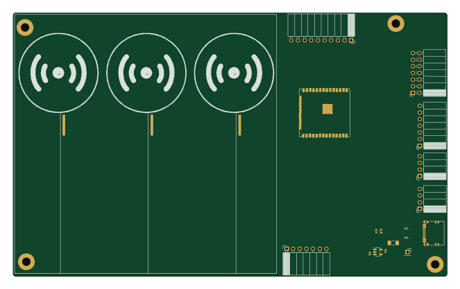 ESP32
Intelligent-Traffic-Simulator
LimesKey
165.5 × 100.5 mm148 parts4LApache-2.01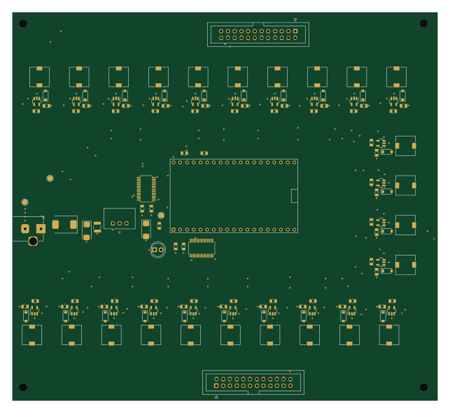 ESP32
Schemav2
rayanyahiaoui13
160.5 × 146.5 mm139 parts2LGPL-3.01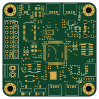
Flight-Controller
AditiLonkadi
50 × 50 mm76 parts4LNo license1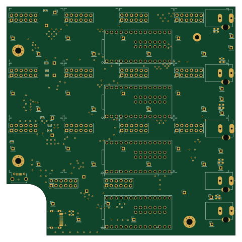 NXP
MotorHub5x5
AxLab-UofC
120 × 120 mm69 parts2LMIT1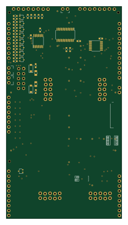
KoloredVerb.core
marcoallegretti
59.6 × 109.5 mm65 parts2LCustom license1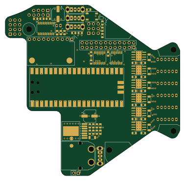
WildWillyR5Hardware
dkjonas
94.4 × 92.2 mm52 parts4LNo license1- schematic only · 67 partsESP32
Prosthetic
SoumyadeepXD
67 partsNo license1 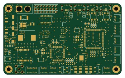
Hades
david-who
100.1 × 60.2 mm187 parts4LBSD-3-Clause0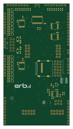
Kivu12
GKeyMaster
59.6 × 109.5 mm135 parts2LCC-BY-SA-4.00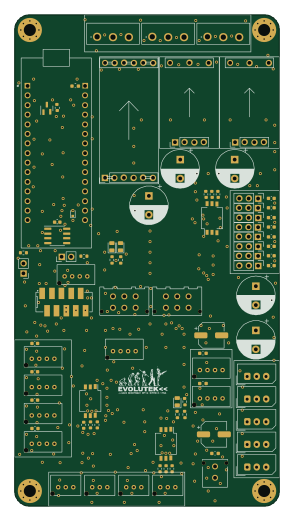
V2
evolutek
70 × 130 mm121 parts2LNo license0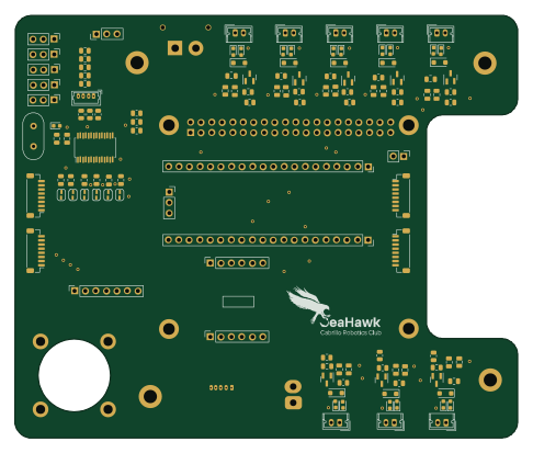
Pi PCB Hat
CabrilloRoboticsClub
121.4 × 102.1 mm117 parts4LMIT0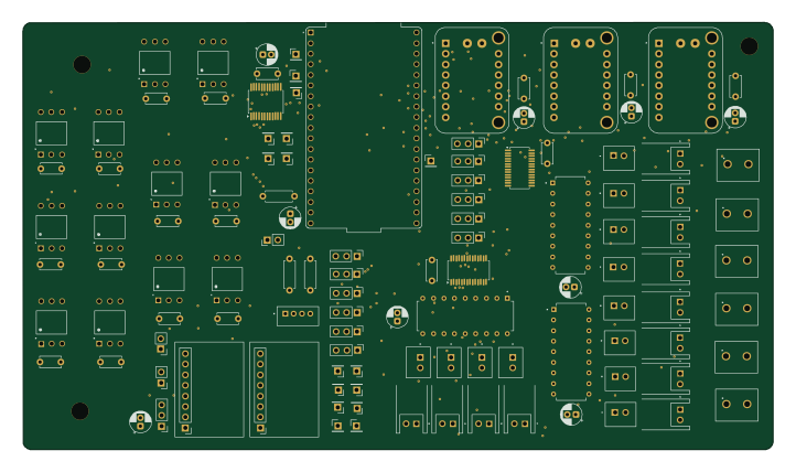 ESP32
Bigthemio
 techandpeople180.1 × 102.5 mm117 parts4LGPL-3.00
 Raspberry Pi
Dart hat
kemfic
114 × 65 mm111 parts4LNo license0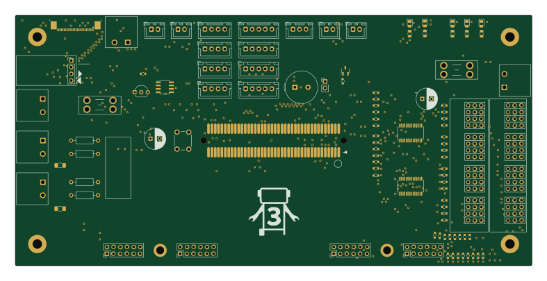
Kevinbot p2 board
Kevinbot-Robotics
196.5 × 95.4 mm110 parts2LCERN-OHL-S-2.00
How designs wire the PCA9685PW
Read from the KiCad layouts of 66 open source designs, one per repository: what each pin of the PCA9685PW connects to, and the resistors, capacitors and other passives placed on it.
- The VDD pin has a decoupling capacitor on 49 of 64 designs, most often 100 nF (then 10 µF).
- The SDA pin has a pull-up to 3.3V on 42 of 64 designs, most often 4.7 kΩ (then 10 kΩ).
- The SCL pin has a pull-up to 3.3V on 41 of 64 designs, most often 4.7 kΩ (then 10 kΩ).
- The EXTCLK pin is tied to GND on 44 of 64 designs (not connected on 13, a signal on 7).
| Pin | Connected to | Parts on the pin |
|---|---|---|
| LED0pin 6 | Connected to: A connector 35% |
|
| LED1pin 7 | Connected to: A connector 36% |
|
| LED2pin 8 | Connected to: A connector 36% |
|
| LED3pin 9 | Connected to: A connector 33% |
|
| LED4pin 10 | Connected to: A connector 32% |
|
| LED5pin 11 | Connected to: A connector 32% · not connected 17% |
|
| LED6pin 12 | Connected to: A connector 31% · not connected 20% |
|
| LED7pin 13 | Connected to: A connector 28% · not connected 23% |
|
| VSSpin 14 | Connected to: GND 98% | — |
| LED8pin 15 | Connected to: A connector 23% · not connected 31% |
|
| LED9pin 16 | Connected to: A connector 22% · not connected 33% |
|
| LED11pin 18 | Connected to: Signal 61% · not connected 39% |
|
| LED12pin 19 | Connected to: Signal 56% · not connected 44% |
|
| OEpin 23 | Connected to: Signal 53% · GND 41% |
|
| EXTCLKpin 25 | Connected to: GND 69% · not connected 20% | — |
| SCLpin 26 | Connected to: A connector 45%, the microcontroller 28% |
|
| SDApin 27 | Connected to: A connector 45%, the microcontroller 28% |
|
| VDDpin 28 | Connected to: 3.3V 95% |
|
10 more pins vary from design to design. Connections count pins, parts count designs; values in brackets are how many parts had that value. Designs read include Kivu12 by ohmtech-rdi, Sycamore by tpcarlson, UaBrain gm e38 by rusefi and 1 Distribution Board by basicallysource.
The PCA9685PW in open source designs
The gallery holds 88 open source boards using the PCA9685PW from 72 GitHub repositories; a typical one measures about 91.8 × 79.5 mm and carries around 83 components.
67% are two-layer designs, the rest use four layers or more, and 49% carry an open source license.
The most starred is Kivu12 by ohmtech-rdi.
Parts used alongside the PCA9685PW
Microcontrollers on boards using the PCA9685PW
What boards using the PCA9685PW are built for
PCA9685PW: common questions
Where can I find a PCA9685PW reference design?
Each of the 88 boards on this page is a real design using the PCA9685PW. Open one to see how it is wired up, with the full BOM, a render of the layout and links to its KiCad files.
What decoupling capacitors do designs use on the PCA9685PW VDD pin?
The VDD pin has a decoupling capacitor on 49 of 64 designs, most often 100 nF (then 10 µF). Counted from the KiCad layouts of 66 open source designs using the PCA9685PW.
What pull-up resistor is used on the PCA9685PW SDA pin?
The SDA pin has a pull-up to 3.3V on 42 of 64 designs, most often 4.7 kΩ (then 10 kΩ). Counted from the KiCad layouts of 66 open source designs using the PCA9685PW.
What pull-up resistor is used on the PCA9685PW SCL pin?
The SCL pin has a pull-up to 3.3V on 41 of 64 designs, most often 4.7 kΩ (then 10 kΩ). Counted from the KiCad layouts of 66 open source designs using the PCA9685PW.
What parts are used alongside the PCA9685PW?
The BMI088, USBLC6-2SC6, 24CW1280T-I/OT, 4051 and ADS1115IDGSR appear in the most repositories here.
Which microcontrollers do boards using the PCA9685PW use?
Most are built on ESP32 (18), Raspberry Pi (7), RP2040/RP2350 (5) and STM32 (4).
How big is a typical board using the PCA9685PW?
The median is 91.8 × 79.5 mm, and 67% are two-layer designs.
What is the most popular open source board using the PCA9685PW?
By GitHub stars, Kivu12 by ohmtech-rdi, with 405 stars.
Can I simulate one of these boards using the PCA9685PW before building it?
Yes. HardLabs turns a board's netlist and BOM into a working simulation, so you can boot and test firmware against it with no hardware on your desk.