
STM32G474-Power-Charger

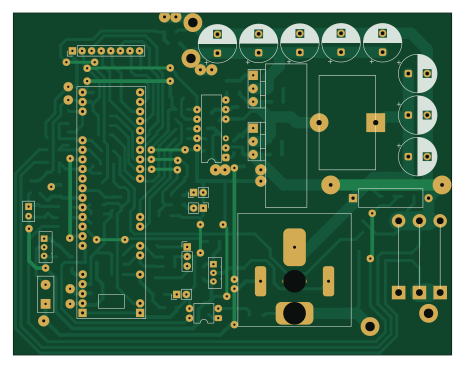
About the STM32G474-Power-Charger PCB
STM32G474-Power-Charger is an open source PCB design by Aleksei327, published on GitHub. It is a 2-layer board measuring 116 × 90.5 mm, with 134 components from 49 distinct parts.
Other key parts include the IR2113, WeAct_STM32G474CEU6_MiniCore, LM2596S-ADJ(12V), AMS1117-3.3V and PC817. By type, the board carries 52 resistors, 45 capacitors, 18 diodes, 6 connectors, 5 ICs and 4 transistors.
It belongs with the power & battery designs in this gallery.
From the project
Experimental STM32G474-based high-current battery charger and programmable synchronous buck converter. KiCad hardware and STM32CubeIDE firmware.
The hardware is an STM32G474-controlled synchronous buck converter fed by a modified ATX power supply.
The PCB file contains the main converter board and several small auxiliary board sections in one drawing. This is why the 3D top/bottom render shows separated islands.
The assembled prototype includes hand wiring and component changes made during bring-up. Photographs and engineering notes document that state, but the KiCad layout must still be reviewed against the actual unit before another board is manufactured.
Main components on the STM32G474-Power-Charger
STM32G474-Power-Charger bill of materials (BOM)
134 components, 49 distinct parts.
| Qty | Part | Footprint | Refs |
|---|---|---|---|
| 1 | IR2113 | DIP-14_W7.62mm | U1 |
| 1 | WeAct_STM32G474CEU6_MiniCore | WeAct_STM32G474CEU6_MiniCore | U2 |
| 1 | LM2596S-ADJ(12V) | TO-263-5_TabPin3 | U4 |
| 1 | AMS1117-3.3V | SOT-223-3_TabPin2 | U5 |
| 1 | PC817 | DIP-4_W7.62mm | U6 |
| 2 | IRFB4110 | TO-220-3_Vertical | Q1, Q2 |
| 2 | D882 | TO-126-3_Vertical | Q4, Q5 |
| 1 | LCD_ST7735 | PinHeader_1x08_P2.54mm_Vertical | J1 |
| 1 | ENCODER | PinHeader_1x03_P2.54mm_Vertical | J2 |
| 1 | BTN_RESET | PinHeader_1x02_P2.54mm_Vertical | J3 |
| 1 | BTN_MENU | PinHeader_1x02_P2.54mm_Vertical | J4 |
| 1 | BTN_START | PinHeader_1x02_P2.54mm_Vertical | J5 |
| 1 | FAN | Fan_2Wire_P5.08mm_WireOrTerminal | J6 |
| 1 | JD1914 | Relay_JD1914_30x30mm_TabSlots_Draft | K1 |
| 1 | Thermistor_NTC | Thermistor_2Pin_P2.54mm_WirePads | TH1 |
| 2 | SS14 | D_SMA | D2, D5 |
| 1 | B340 | D_SMC | D3 |
| 15 | 1N4148 | D_MiniMELF | D4, D6, D7, D8, D9, D10, D11, D12 +7 |
| 1 | 68uH | L_THT_LM2596_15x10mm_P10.00mm | L1 |
| 1 | 22uH | L_THT_Power_25x15mm_P20.00mm_H25mm | L2 |
Show 29 more
| Qty | Part | Footprint | Refs |
|---|---|---|---|
| 2 | 330uF | CP_Radial_D10.0mm_P5.00mm | C1, C2 |
| 2 | 220uF | CP_Radial_D10.0mm_P5.00mm | C5, C6 |
| 18 | 100nF | C_1206_3216Metric_Pad1.33x1.80mm_HandSolder | C7, C8, C9, C10, C24, C27, C28, C29 +10 |
| 8 | 470uF | CP_Radial_D10.0mm_P5.00mm | C11, C17, C18, C19, C20, C39, C40, C41 |
| 4 | 10uF | CP_Radial_D5.0mm_P2.0-3.5mm_H11mm_Hand | C13, C14, C15, C16 |
| 2 | 10nF | C_1206_3216Metric_Pad1.33x1.80mm_HandSolder | C21, C26 |
| 2 | 10uF | C_1210_3225Metric_Pad1.33x2.70mm_HandSolder | C22, C42 |
| 3 | 1uF | C_1206_3216Metric_Pad1.33x1.80mm_HandSolder | C23, C34, C43 |
| 1 | 2nF | C_1206_3216Metric_Pad1.33x1.80mm_HandSolder | C32 |
| 2 | 470pF | C_1206_3216Metric_Pad1.33x1.80mm_HandSolder | C36, C37 |
| 1 | 4.7uF | C_1206_3216Metric_Pad1.33x1.80mm_HandSolder | C46 |
| 1 | 0 Om | R_1206_3216Metric_Pad1.30x1.75mm_HandSolder | R00 |
| 1 | 1,2 kOm | R_1206_3216Metric_Pad1.30x1.75mm_HandSolder | R1 |
| 1 | 10,5 kOm | R_1206_3216Metric_Pad1.30x1.75mm_HandSolder | R2 |
| 1 | 680 | R_Axial_D5.0mm_P20.00mm_2W | R3 |
| 2 | 100kOm | R_1206_3216Metric_Pad1.30x1.75mm_HandSolder | R4, R48 |
| 3 | 0.01 | Shunt_U_Constantan_D1.5mm_P19.00mm_H10.00mm | R6, R10, R11 |
| 1 | 180kOm | R_1206_3216Metric_Pad1.30x1.75mm_HandSolder | R7 |
| 1 | 220 | R_1206_3216Metric_Pad1.30x1.75mm_HandSolder | R8 |
| 10 | 100 | R_1206_3216Metric_Pad1.30x1.75mm_HandSolder | R12, R13, R16, R17, R18, R19, R20, R29 +2 |
| 2 | 1kOm | R_1206_3216Metric_Pad1.30x1.75mm_HandSolder | R14, R52 |
| 14 | 10kOm | R_1206_3216Metric_Pad1.30x1.75mm_HandSolder | R15, R31, R32, R35, R36, R40, R41, R42 +6 |
| 1 | 200kOm | R_1206_3216Metric_Pad1.30x1.75mm_HandSolder | R21 |
| 3 | 22kOm | R_1206_3216Metric_Pad1.30x1.75mm_HandSolder | R22, R27, R28 |
| 4 | 4.7kOm | R_1206_3216Metric_Pad1.30x1.75mm_HandSolder | R23, R25, R26, R47 |
| 1 | 6.8kOm | R_1206_3216Metric_Pad1.30x1.75mm_HandSolder | R24 |
| 4 | 10 | R_1206_3216Metric_Pad1.30x1.75mm_HandSolder | R33, R34, R38, R39 |
| 1 | 1kOm | R_Axial_D5.0mm_P20.00mm_2W | R46 |
| 1 | 470 | R_1206_3216Metric_Pad1.30x1.75mm_HandSolder | R50 |
STM32G474-Power-Charger design files
The KiCad project lives in the Aleksei327/STM32G474-Power-Charger repository on GitHub; these links point at the commit this page was built from.
STM32G474-Power-Charger: common questions
How big is the STM32G474-Power-Charger PCB?
The STM32G474-Power-Charger measures 116 × 90.5 mm, has 2 copper layers and is 1.6 mm thick.
How many components are on the STM32G474-Power-Charger?
134 components, from 49 distinct parts. The full bill of materials is listed on this page.
Where can I download the STM32G474-Power-Charger design files?
From the Aleksei327/STM32G474-Power-Charger repository on GitHub, which has the KiCad layout and the schematic; the links under Design files point to each one.
Can I use the STM32G474-Power-Charger design in my own project?
The repository has no license, so all rights stay with Aleksei327. Use it as a reference, and ask the author before reusing the design.
Similar boards

Stack chan
stack-chan
50 × 50 mm33 parts2LApache-2.01.7k
Display Carrier
AxxAxx
35.6 × 58.2 mm5 parts2LGPL-3.01.7k
ControllerCurrentShuntAddOn
stuartpittaway
26 × 16.9 mm9 parts2LCC-BY-NC-4.01.1k
Module 16S PassiveBalanceAddOn
61 × 74 mm86 parts2LCC-BY-NC-4.01.1k
TemperaturePCB PANEL
116 × 75.5 mm178 parts2LCC-BY-NC-4.01.1k
ProgrammingAdapter
10.5 × 83 mm3 parts2LCC-BY-NC-4.01.1k