
Remora

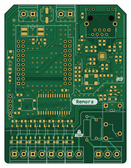
About the Remora PCB
Remora is an open source ESP32 PCB design by alexthomazo, published on GitHub. It is a 2-layer board measuring 66 × 86 mm, with 105 components from 42 distinct parts.
Its main chip is the ESP32-D1-MINI, from the ESP32 family. Other key parts include the TLP267J, MCP23017_SO, LTV-814S and LAN8720A. By type, the board carries 41 resistors, 18 ICs, 17 diodes, 11 capacitors, 9 connectors and 2 transistors.
It belongs with the iot & wireless designs in this gallery.
From the project
Contrôleur fil pilote permettant de contrôler 7 zones et un relai.
Contrôleur fil pilote permettant de contrôler 7 zones et un relai.
Version 2.0 de Remora basé sur https://github.com/tducret/programmateur-fil-pilote-wifi/tree/master
ESP32 Mini D1 MCP23017 pour le contrôle des 7 zones et du relai Port ethernet optionnel Connecteur I2C pour ecran OLED * Relai permettant le contrôle d'un connecteur heures pleines/creuses
Changements depuis la version 1.3 ---------------------------------
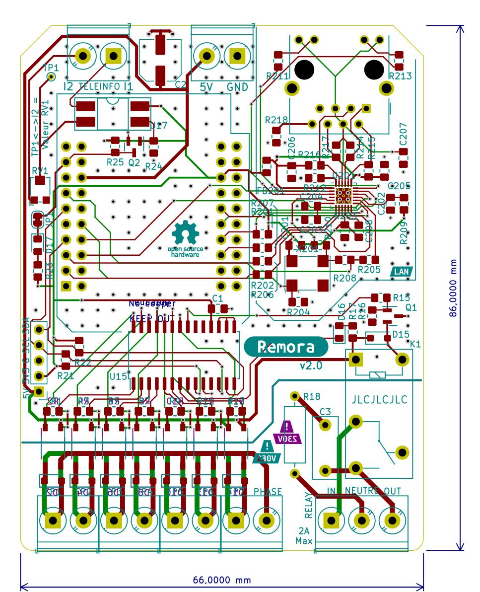
Main components on the Remora
Remora bill of materials (BOM)
105 components, 42 distinct parts.
| Qty | Part | Footprint | Refs |
|---|---|---|---|
| 14 | TLP267J | MFSOP6-4_4.4x3.6mm_P1.27mm | U1, U2, U3, U4, U5, U6, U7, U8 +6 |
| 1 | MCP23017_SO | SOIC-28W_7.5x17.9mm_P1.27mm | U15 |
| 1 | ESP32-D1-MINI | ESP32-D1-MINI | U16 |
| 1 | LTV-814S | DIP-4_W8.89mm_SMDSocket_LongPads | U17 |
| 1 | LAN8720A | VQFN-24-1EP_4x4mm_P0.5mm_EP2.5x2.5mm | U201 |
| 1 | MMBT2222 | SOT-23 | Q1 |
| 1 | BSS138 | SOT-23 | Q2 |
| 1 | 50M | Oscillator_SMD_Abracon_ASV-4Pin_7.0x5.1mm | X201 |
| 1 | ST_01x03 | TerminalBlock_Phoenix_PT-1,5-3-5.0-H_1x03_P5.00mm_Horizontal | J1 |
| 6 | ST_01x02 | TerminalBlock_Phoenix_PT-1,5-2-5.0-H_1x02_P5.00mm_Horizontal | J2, J3, J4, J5, J6, J9 |
| 1 | Conn_01x05_Pin | PinHeader_1x05_P2.54mm_Vertical | J7 |
| 1 | RJ45_HanRun_HR911105A | RJ45_Hanrun_HR911105A_Horizontal | J8 |
| 1 | Jumper_LED | SolderJumper-2_P1.3mm_Bridged_RoundedPad1.0x1.5mm | JP1 |
| 1 | G5Q-1 | Relay_SPDT_Omron-G5Q-1 | K1 |
| 1 | 2k | Potentiometer_Bourns_TC33X_Vertical | RV1 |
| 1 | SW_Push | SW_Push_1P1T_NO_6x6mm_H9.5mm | SW1 |
| 1 | TestPoint | TestPoint_THTPad_D1.0mm_Drill0.5mm | TP1 |
| 15 | 1N4007 | D_SOD-123FL | D1, D2, D3, D4, D5, D6, D7, D8 +7 |
| 1 | LED Red | LED_0805_2012Metric_Pad1.15x1.40mm_HandSolder | D16 |
| 1 | LED Blue | LED_0805_2012Metric_Pad1.15x1.40mm_HandSolder | D17 |
Show 22 more
| Qty | Part | Footprint | Refs |
|---|---|---|---|
| 1 | 2.0A/0.050 DCR | L_0805_2012Metric_Pad1.15x1.40mm_HandSolder | FB201 |
| 5 | 100n | C_0805_2012Metric_Pad1.18x1.45mm_HandSolder | C1, C201, C202, C205, C206 |
| 1 | 47u | C_Elec_6.3x5.4 | C2 |
| 1 | 100n | C_Rect_L11.5mm_W5.6mm_P10.00mm_MKT | C3 |
| 1 | 1u | C_0805_2012Metric_Pad1.18x1.45mm_HandSolder | C203 |
| 1 | 470p | C_0805_2012Metric_Pad1.18x1.45mm_HandSolder | C204 |
| 2 | 10n | C_0805_2012Metric_Pad1.18x1.45mm_HandSolder | C207, C208 |
| 14 | 680R | R_0805_2012Metric_Pad1.20x1.40mm_HandSolder | R1, R2, R3, R4, R5, R6, R7, R8 +6 |
| 1 | 1k | R_0805_2012Metric_Pad1.20x1.40mm_HandSolder | R15 |
| 3 | 10k | R_0805_2012Metric_Pad1.20x1.40mm_HandSolder | R16, R25, R204 |
| 1 | 430R | R_0805_2012Metric_Pad1.20x1.40mm_HandSolder | R17 |
| 1 | 220R - 1/2W | R_Axial_DIN0309_L9.0mm_D3.2mm_P12.70mm_Horizontal | R18 |
| 3 | 3k3 | R_0805_2012Metric_Pad1.20x1.40mm_HandSolder | R21, R22, R24 |
| 1 | 330R | R_0805_2012Metric_Pad1.20x1.40mm_HandSolder | R23 |
| 1 | 1k5 | R_0805_2012Metric_Pad1.20x1.40mm_HandSolder | R201 |
| 4 | 10R | R_0805_2012Metric_Pad1.20x1.40mm_HandSolder | R202, R203, R206, R207 |
| 3 | 33R | R_0805_2012Metric_Pad1.20x1.40mm_HandSolder | R205, R208, R210 |
| 1 | 4k7 | R_0805_2012Metric_Pad1.20x1.40mm_HandSolder | R209 |
| 2 | 120R | R_0805_2012Metric_Pad1.20x1.40mm_HandSolder | R211, R213 |
| 1 | 12k1 / 1% | R_0805_2012Metric_Pad1.20x1.40mm_HandSolder | R212 |
| 4 | 49R9 | R_0805_2012Metric_Pad1.20x1.40mm_HandSolder | R214, R215, R216, R217 |
| 1 | 0R | R_0805_2012Metric_Pad1.20x1.40mm_HandSolder | R218 |
Remora design files
The KiCad project lives in the alexthomazo/remora repository on GitHub; these links point at the commit this page was built from.
- Layoutremora.kicad_pcb
- Schematicremora.kicad_sch
Remora: common questions
What microcontroller does the Remora use?
The Remora is built around the ESP32-D1-MINI, from the ESP32 family.
How big is the Remora PCB?
The Remora measures 66 × 86 mm, has 2 copper layers and is 1.6 mm thick.
How many components are on the Remora?
105 components, from 42 distinct parts. The full bill of materials is listed on this page.
Where can I download the Remora design files?
From the alexthomazo/remora repository on GitHub, which has the KiCad layout and the schematic; the links under Design files point to each one.
Can I use the Remora design in my own project?
The repository has no license, so all rights stay with alexthomazo. Use it as a reference, and ask the author before reusing the design.
Can I test firmware for the Remora without the hardware?
Yes. HardLabs builds a simulation of the board from its netlist and BOM, so you can run and debug ESP32 firmware against it before you order a PCB.
Similar boards
 ESP32
OSO-BOOK-B1
joeycastillo
85 × 115 mm65 parts2LCC-BY-SA-4.08.1k ESP32
Powertrain
byrantech
64 × 45.4 mm171 parts4LMIT4.3k ESP32
Badge
atopile
56.3 × 39 mm239 parts4LMIT4.0k ESP32
Esp32 minimal
36.2 × 26.8 mm20 parts2LMIT4.0k ESP32
Controller
StuckAtPrototype
29 × 74 mm58 parts4LApache-2.03.8k ESP32
Racer
36 × 50.2 mm70 parts4LApache-2.03.8k