
Harp.device.PhotodiodeBoard

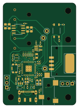
About the Harp.device.PhotodiodeBoard PCB
Harp.device.PhotodiodeBoard is an open source RP2040/RP2350 PCB design by AllenNeuralDynamics, published on GitHub. It is a 4-layer board measuring 38 × 53 mm, with 61 components from 32 distinct parts.
Its main chip is the RP2040, from the RP2040/RP2350 family. Other key parts include the TPD2EUSB30, LP2985-3.3, W25Q16JVUXIQ, AD8656 and REF2033AIDDCR. By type, the board carries 25 capacitors, 12 resistors, 7 ICs, 5 connectors, 5 diodes and 3 test points.
From the project
0374: Harp photodiode board with automated comparator calibration and gamma calibration developed by SIPE.
These schematic and layout designs have been vetted on prior devices.
High Level Specs: USBC connector (ESD protected with TVS diode). Audio jack connector for Harp synchronization signal (ESD protected with TVS diode).
Component Specs: aqueous washable commonly available components (no end-of-life or last-time-buy)
Layout Specs: 4-layer PCB signal (top), ground, power, signal (bottom) 6-mil traces, 6-mil spacing (0.1524mm) no microvias smallest resistor/capacitor sizes are 0402. Footprints default to "non-hand-soldering"-style.
Main components on the Harp.device.PhotodiodeBoard
Harp.device.PhotodiodeBoard bill of materials (BOM)
61 components, 32 distinct parts.
| Qty | Part | Footprint | Refs |
|---|---|---|---|
| 1 | TPD2EUSB30 Texas Instruments | Texas_DRT-3 | U1 |
| 1 | LP2985-3.3 Texas Instruments | SOT-23-5 | U2 |
| 1 | RP2040 Raspberry Pi | QFN56_7X7_RPI | U3 |
| 1 | W25Q16JVUXIQ Winbond Electronics | USON-8_UX_2x3x0p6_WIN | U4 |
| 1 | AD8656 Analog Devices Inc. | R_8_ADI | U5 |
| 1 | REF2033AIDDCR Texas Instruments | DDC0005A_M | U6 |
| 1 | Optocoupler_DC_PhotoNPN_AKEC Lite-On Inc. | MFSOP6-4_4.4x3.6mm_P1.27mm | U7 |
| 1 | ECS-TXO-2016 ECS Inc. | Crystal_SMD_2016-4Pin_2.0x1.6mm | X1 |
| 1 | Conn_01x04_Pin 3M | Connector_3M_MiniClamp_4_37204-1BE0-004PL | J1 |
| 1 | AudioJack3 | CUI_SJ-3524-SMT-BE | J2 |
| 1 | USB_C_Receptacle_USB2.0 JAE Electronics | USB_C_Receptacle_JAE_DX07S016JA1R1500 | J3 |
| 2 | ~ | PinHeader_1x03_P2.54mm_Vertical | J4, J5 |
| 2 | BPW21R Vishay Semiconductor Opto Division | TO99_BPW20RF_VIS | CR1, CR2 |
| 1 | ~ Würth Elektronik | 435451019820 | SW2 |
| 3 | TestPoint | TestPoint_Loop_D2.50mm_Drill1.0mm | TP1, TP2, TP3 |
| 2 | D_TVS onsemi | D_0201_0603Metric | D1, D2 |
| 2 | LED SunLED | LED_0603_1608Metric_Pad1.05x0.95mm_HandSolder | D3, D4 |
| 1 | BAT54J MCC (Micro Commercial Components) | D_SOD-323F | D5 |
| 15 | 100nF Walson Technology Corporation | C_0402_1005Metric | C1, C2, C6, C8, C13, C14, C15, C16 +7 |
| 2 | 10pF KEMET | C_0805_2012Metric_Pad1.18x1.45mm_HandSolder | C3, C5 |
Show 12 more
| Qty | Part | Footprint | Refs |
|---|---|---|---|
| 2 | 10nF Murata Electronics | C_0402_1005Metric | C4, C21 |
| 4 | 1uF KYOCERA AVX | C_0402_1005Metric | C9, C10, C11, C22 |
| 1 | 10uF Cal-Chip Electronics, Inc. | C_0805_2012Metric | C12 |
| 1 | 2.2uF Cal-Chip Electronics, Inc. | C_0402_1005Metric | C23 |
| 1 | 1K Yageo | R_0402_1005Metric | R1 |
| 2 | 5K1 Yageo | R_0402_1005Metric | R2, R3 |
| 1 | 487 Vishay Dale | R_0402_1005Metric | R4 |
| 1 | 4.7k YAGEO | R_0402_1005Metric | R5 |
| 2 | 390k | R_0805_2012Metric_Pad1.20x1.40mm_HandSolder | R6, R7 |
| 1 | 10K KOA Speer Electronics, Inc. | R_0402_1005Metric | R8 |
| 2 | 27 Yageo | R_0402_1005Metric | R9, R10 |
| 2 | 330 Panasonic Electronic Components | R_0402_1005Metric | R11, R12 |
Harp.device.PhotodiodeBoard design files
The KiCad project lives in the AllenNeuralDynamics/harp.device.PhotodiodeBoard repository on GitHub; these links point at the commit this page was built from.
Harp.device.PhotodiodeBoard: common questions
What microcontroller does the Harp.device.PhotodiodeBoard use?
The Harp.device.PhotodiodeBoard is built around the RP2040, from the RP2040/RP2350 family.
How big is the Harp.device.PhotodiodeBoard PCB?
The Harp.device.PhotodiodeBoard measures 38 × 53 mm, has 4 copper layers and is 1.6 mm thick.
How many components are on the Harp.device.PhotodiodeBoard?
61 components, from 32 distinct parts. The full bill of materials is listed on this page.
Where can I download the Harp.device.PhotodiodeBoard design files?
From the AllenNeuralDynamics/harp.device.PhotodiodeBoard repository on GitHub, which has the KiCad layout and the schematic; the links under Design files point to each one.
Can I use the Harp.device.PhotodiodeBoard design in my own project?
The repository has no license, so all rights stay with AllenNeuralDynamics. Use it as a reference, and ask the author before reusing the design.
Can I test firmware for the Harp.device.PhotodiodeBoard without the hardware?
Yes. HardLabs builds a simulation of the board from its netlist and BOM, so you can run and debug RP2040/RP2350 firmware against it before you order a PCB.
Similar boards
 RP2040/RP2350
Open Book Abridged Edition
joeycastillo
85 × 115 mm29 parts2LCC-BY-SA-4.08.1k RP2040/RP2350
Corne
foostan
277.2 × 107.5 mm164 parts2LCC-BY-4.07.7k RP2040/RP2350
Corne
277.2 × 107.5 mm164 parts2LCC-BY-4.07.7k RP2040/RP2350
LogicAnalyzer
gusmanb
57 × 55.2 mm6 parts2LGPL-3.05.0k RP2040/RP2350
Jitx design
55.5 × 65 mm26 parts4LGPL-3.05.0k RP2040/RP2350
Main
google
98 × 71 mm102 parts2LApache-2.02.9k