
Gpsdo

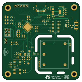
About the Gpsdo PCB
Gpsdo is an open source STM32 PCB design by AndreasArendt, published on GitHub under the MIT license. It is a 4-layer board measuring 70 × 70 mm, with 71 components from 24 distinct parts.
Its main chip is the STM32F411CEUx, from the STM32 family. Other key parts include the SN74LVC1T45DCK, REF5040AD, AD5541A, OPA197xD and AMS1117-3.3. By type, the board carries 40 capacitors, 14 resistors, 9 ICs, 3 diodes, 2 connectors and 1 crystal.
It belongs with the rf & radio designs in this gallery.
From the project
Low cost GPS Disciplined Oscillator
GPSDO (GPS Disciplined Oscillator) combines the precision of a high-quality OCXO (Oven-Controlled Crystal Oscillator) with the pulse-per-second (PPS) signal from a GNSS receiver. The goal is to achieve accurate time and frequency reference, down to the nanosecond level.
This project aims to create an open-source and affordable GPSDO from scratch, including designing custom hardware (PCB) and developing the supporting software.
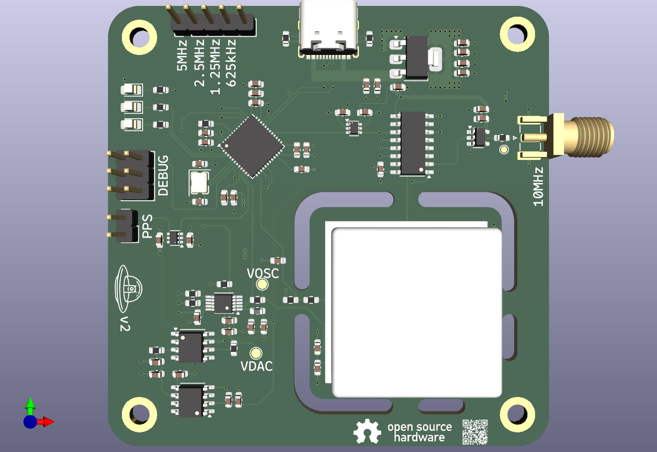
Main components on the Gpsdo
Gpsdo bill of materials (BOM)
71 components, 24 distinct parts.
| Qty | Part | Footprint | Refs |
|---|---|---|---|
| 2 | SN74LVC1T45DCK | SOT-363_SC-70-6 | U1, U2 |
| 1 | REF5040AD | SOIC-8_3.9x4.9mm_P1.27mm | U3 |
| 1 | AD5541A | MSOP-10_3x3mm_P0.5mm | U4 |
| 1 | OPA197xD | SOIC-8_3.9x4.9mm_P1.27mm | U5 |
| 1 | STM32F411CEUx | QFN-48-1EP_7x7mm_P0.5mm_EP5.6x5.6mm | U6 |
| 1 | AMS1117-3.3 | SOT-223-3_TabPin2 | U7 |
| 1 | 74HC161 | SO-16_3.9x9.9mm_P1.27mm | U8 |
| 1 | SN74LVC1G125DBV | SOT-23-5 | U9 |
| 1 | X322516MLB4SI | Crystal_SMD_3225-4Pin_3.2x2.5mm | X1 |
| 1 | USB_C_Receptacle_USB2.0_14P | USB_C_Receptacle_G-Switch_GT-USB-7010ASV | J3 |
| 1 | Conn_01x05 | PinHeader_1x05_P2.54mm_Vertical | J7 |
| 1 | NTCG103JF103FT1 | R_0603_1608Metric | TH1 |
| 3 | LED | LED_0805_2012Metric_Pad1.15x1.40mm_HandSolder | D1, D2, D3 |
| 1 | 10uH | L_0603_1608Metric | L1 |
| 26 | 100n | C_0603_1608Metric | C1, C2, C4, C5, C7, C8, C9, C11 +18 |
| 6 | 10u | C_0603_1608Metric | C3, C10, C13, C28, C29, C30 |
| 4 | 1u | C_0603_1608Metric | C6, C12, C26, C36 |
| 2 | 12p | C_0603_1608Metric | C16, C17 |
| 2 | 4.7u | C_0603_1608Metric | C18, C25 |
| 3 | 100 | R_0603_1608Metric | R1, R5, R6 |
Show 4 more
| Qty | Part | Footprint | Refs |
|---|---|---|---|
| 3 | 33 | R_0603_1608Metric | R4, R8, R18 |
| 3 | 10k | R_0603_1608Metric | R7, R9, R17 |
| 3 | 1.1k | R_0603_1608Metric | R12, R13, R14 |
| 2 | 22k | R_0603_1608Metric | R15, R16 |
Gpsdo design files
The KiCad project lives in the AndreasArendt/gpsdo repository on GitHub; these links point at the commit this page was built from.
- Layouthardware/gpsdo/gpsdo.kicad_pcb
- Schematichardware/gpsdo/gpsdo.kicad_sch
Gpsdo: common questions
What microcontroller does the Gpsdo use?
The Gpsdo is built around the STM32F411CEUx, from the STM32 family.
How big is the Gpsdo PCB?
The Gpsdo measures 70 × 70 mm, has 4 copper layers and is 1.6 mm thick.
How many components are on the Gpsdo?
71 components, from 24 distinct parts. The full bill of materials is listed on this page.
Where can I download the Gpsdo design files?
From the AndreasArendt/gpsdo repository on GitHub, which has the KiCad layout and the schematic; the links under Design files point to each one.
Can I use the Gpsdo design in my own project?
Yes, under the terms of its MIT license, which AndreasArendt chose for the repository.
Can I test firmware for the Gpsdo without the hardware?
Yes. HardLabs builds a simulation of the board from its netlist and BOM, so you can run and debug STM32 firmware against it before you order a PCB.
Similar boards
 STM32
LumenPnP Motherboard
opulo-inc
149 × 95 mm296 parts4LCC-BY-SA-4.03.7k STM32
Base
google
52.3 × 52.3 mm36 parts2LApache-2.02.9k STM32
Type g
169 × 30 mm24 parts2LApache-2.02.9k STM32
Main panel
234 × 84 mm26 parts4LApache-2.02.9k STM32
Type a
150 × 30 mm14 parts2LApache-2.02.9k STM32
Type c
188 × 30 mm17 parts2LApache-2.02.9k