
SenseCam Adapter rev1

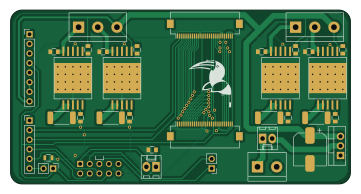
About the SenseCam Adapter rev1 PCB
SenseCam Adapter rev1 is an open source Nordic nRF PCB design by Appiko, published on GitHub under the CERN-OHL-1.2 license. It is a 2-layer board measuring 90 × 46 mm, with 36 components from 29 distinct parts.
Its main chip is the MDBT42Q, from the Nordic nRF family. Other key parts include the TLV8802 and STCS2A. By type, the board carries 14 capacitors, 9 connectors, 5 resistors, 4 ICs, 2 switches and 1 transistor.
From the project
This repository contains all the KiCad based PCB design and related documentation for all the PCBs developed at Appiko.
This repository contains all the KiCad based PCB design and related documentation for all the circuit boards developed at Appiko.
All the design files are licensed using CERN Open Hardware Licence v1.2.
Main components on the SenseCam Adapter rev1
SenseCam Adapter rev1 bill of materials (BOM)
36 components, 29 distinct parts — part numbers from the project's BOM.
| Qty | Part | Footprint | Refs |
|---|---|---|---|
| 1 | TLV8802 STCS2A | STCS2A_PowerSO-10 | U1 |
| 1 | MDBT42Q STCS2A | STCS2A_PowerSO-10 | U2 |
| 2 | STCS2A | STCS2A_PowerSO-10 | U3, U4 |
| 1 | TSM2301/IRLML6401 IRF9540 | TO-220-3_Vertical | Q1 |
| 1 | AUDIO-JACK-4 Conn_01x30 | ArduCam_FPC_30pin_P0.50mm_Horizontal | J1 |
| 1 | Conn_01x30 | Hirose_FH12-30S-0.5SH_1x30-1MP_P0.50mm_Horizontal | J2 |
| 1 | Conn_01x08 | PinHeader_1x08_P2.54mm_Vertical | J3 |
| 1 | Conn_01x06 | PinHeader_1x06_P2.54mm_Vertical | J4 |
| 1 | LDR_CONN | Pin_Header_Straight_1x02_Pitch2.54mm | J5 |
| 2 | Conn_01x03 | TerminalBlock_bornier-3_P5.08mm | J6, J7 |
| 1 | Conn_01x02 | PinHeader_1x02_P2.54mm_Vertical | J8 |
| 1 | CONN_02X05 | Berg_5x2Conn | P1 |
| 1 | LiPo 2s | TerminalBlock_bornier-2_P5.08mm | BT1 |
| 1 | SW_SPST | Molex_KK-6410-02_02x2.54mm_Straight | SW1 |
| 1 | SW_Push | Molex_KK-6410-02_02x2.54mm_Straight | SW2 |
| 1 | 10UF 100uF | CP_Elec_8x10.5 | C1 |
| 1 | 6.8NF 100nF | C_0805 | C2 |
| 2 | 10UF 0.47uF | C_0805 | C3, C4 |
| 1 | 6.8NF 0.1nF | C_0805 | C5 |
| 1 | 100PF 0.1nF | C_0805 | C6 |
Show 9 more
| Qty | Part | Footprint | Refs |
|---|---|---|---|
| 2 | 1UF 0.47uF | C_0805 | C7, C8 |
| 1 | 100NF 0.1nF | C_0805 | C9 |
| 1 | 8PF 0.1nF | C_0805 | C10 |
| 1 | 10UF 100nF | C_0805 | C12 |
| 2 | 100nF | C_0805 | C13, C15 |
| 1 | 100NF 100nF | C_0805 | C14 |
| 1 | 47K 10k | R_0805 | R1 |
| 3 | 47K 0R033 | R_2512_6332Metric_Pad1.52x3.35mm_HandSolder | R2, R4, R5 |
| 1 | 1M5 0R033 | R_2512_6332Metric_Pad1.52x3.35mm_HandSolder | R3 |
SenseCam Adapter rev1 design files
The KiCad project lives in the Appiko/sense_snap_hw repository on GitHub; these links point at the commit this page was built from.
SenseCam Adapter rev1: common questions
What microcontroller does the SenseCam Adapter rev1 use?
The SenseCam Adapter rev1 is built around the MDBT42Q, from the Nordic nRF family.
How big is the SenseCam Adapter rev1 PCB?
The SenseCam Adapter rev1 measures 90 × 46 mm, has 2 copper layers and is 1.6 mm thick.
How many components are on the SenseCam Adapter rev1?
36 components, from 29 distinct parts, with part numbers taken from the project's own BOM. The full bill of materials is listed on this page.
Where can I download the SenseCam Adapter rev1 design files?
From the Appiko/sense_snap_hw repository on GitHub, which has the KiCad layout and the BOM; the links under Design files point to each one.
Can I use the SenseCam Adapter rev1 design in my own project?
Yes, under the terms of its CERN-OHL-1.2 license, which Appiko chose for the repository.
Can I test firmware for the SenseCam Adapter rev1 without the hardware?
Yes. HardLabs builds a simulation of the board from its netlist and BOM, so you can run and debug Nordic nRF firmware against it before you order a PCB.
More boards in sense_snap_hw
 STM32
STM32SenseCam rev1
45 × 70 mm62 parts2LCERN-OHL-1.22 Nordic nRF
SensePi rev5 main
56.5 × 40 mm53 parts2LCERN-OHL-1.22 Nordic nRF
SenseEle SMA rev1
49 × 45 mm51 parts2LCERN-OHL-1.22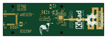 Nordic nRF
SenseEle PCB Antenna rev2
92.7 × 30 mm50 parts2LCERN-OHL-1.22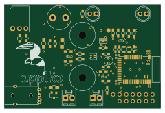 Nordic nRF
SenseBe rev2
60 × 40 mm43 parts2LCERN-OHL-1.22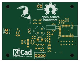 Nordic nRF
Sense rev4
68 × 52 mm41 parts2LCERN-OHL-1.22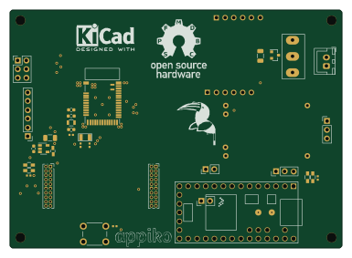 Nordic nRF
SenseRx rev1
96 × 69 mm36 parts2LCERN-OHL-1.22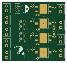 Nordic nRF
STCS2A driver rev1
65 × 61 mm34 parts2LCERN-OHL-1.22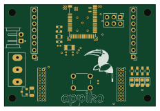 Nordic nRF
Senseble rev1
58 × 39 mm28 parts2LCERN-OHL-1.22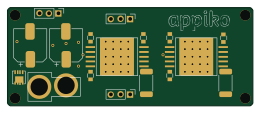 Nordic nRF
SenseCam STCS2A rev1
65 × 26 mm28 parts2LCERN-OHL-1.22
Similar boards
 Nordic nRF
TOTEM
GEIGEIGEIST
258.8 × 94.4 mm85 parts2LCERN-OHL-P-2.02.0k Nordic nRF
Pixl.js
solosky
40 × 23 mm45 parts4LGPL-2.01.4k Nordic nRF
Board
dennisss
363 × 128 mm420 parts4LApache-2.0381 Nordic nRF
Management
101 × 31.5 mm50 parts2LApache-2.0381 Nordic nRF
Board hl15-latest
61 × 37 mm14 parts2LApache-2.0381 Nordic nRF
Mikoto
zhiayang
18 × 33.3 mm53 parts4LApache-2.0355