
JamRF


About the JamRF PCB
JamRF is an open source RP2040/RP2350 PCB design by Arcioth, published on GitHub under the CERN-OHL-P-2.0 license. It is a 4-layer board measuring 120 × 90 mm, with 61 components from 34 distinct parts.
Its main chip is the ESP32-PICO-V3-02, from the RP2040/RP2350 family. Other key parts include the D24V10F5, TPS7A4700, MAX2751, MAX2750 and TGA2215-SM. By type, the board carries 19 capacitors, 17 resistors, 10 ICs, 4 transistors, 3 connectors and 2 fuses.
It belongs with the rf & radio, iot & wireless and power & battery designs in this gallery.
From the project
Dual-band chaos-modulated RF transmitter (GPS L1 + WiFi 2.4 GHz). Open hardware, KiCad 9.0. CERN-OHL-P v2.
JamRF v2 uses a hierarchical schematic design inspired by the HackRF One baseband/frontend separation pattern.
Both RF chains use chaos-modulated VCOs. The ESP32's DAC outputs (G25, G26) drive the TUNE pins of the MAX2751 and MAX2750 VCOs, sweeping them across their respective bands. The chaotic modulation signal spreads spectral energy across the target bandwidth.

Main components on the JamRF
JamRF bill of materials (BOM)
61 components, 34 distinct parts — part numbers from the project's BOM.
| Qty | Part | Footprint | Refs |
|---|---|---|---|
| 1 | ESP32-PICO-V3-02 M5StickC_Plus2 M5Stack | M5StickC_Plus2_Module | U1 |
| 1 | D24V10F5 MAX2751 Pololu | SOT-23-6 | U2 |
| 1 | TPS7A4700 TGA2215-SM Texas Instruments | QFN-32-1EP_5x5mm_P0.5mm_EP3.45x3.45mm | U3 |
| 1 | MAX2751 MAX2750 Maxim Integrated | SOT-23-6 | U4 |
| 1 | MAX2750 ZVE-3W-83+ Maxim Integrated | Mini-Circuits_CP1281 | U5 |
| 1 | TGA2215-SM D24V10F5 Qorvo | Pololu_D24V10F5 | U6 |
| 1 | ZVE-3W-83+ TPS7A4700 Mini-Circuits | Texas_RGP0020H_VQFN-20-1EP_4x4mm_P0.5mm_EP2.4x2.4mm | U7 |
| 1 | LM2776 U3V70F15 Texas Instruments | Pololu_U3V70F15 | U8 |
| 1 | LM393 LM2776 Texas Instruments | SOT-23-6 | U9 |
| 1 | LM393 | SOIC-8_3.9x4.9mm_P1.27mm | U10 |
| 2 | SQJ407EP 2N7002 Vishay | SOT-23 | Q1, Q2 |
| 1 | 2N7002 SQJ407EP ON Semi | PowerPAK_SO-8_Single | Q3 |
| 1 | SQJ407EP | PowerPAK_SO-8_Single | Q4 |
| 1 | 14.8V SMA - | SMA_Amphenol_132289_EdgeMount | J1 |
| 1 | SMA - | SMA_Amphenol_132289_EdgeMount | J2 |
| 1 | 14.8V 4S LiPo - | AMASS_XT60PW-M_1x02_P7.20mm_Horizontal | J3 |
| 1 | BFCN-1575+ Mini-Circuits | Filter_Mini-Circuits_FV1206 | F1 |
| 1 | BFCN-2440+ Mini-Circuits | Filter_Mini-Circuits_FV1206 | F2 |
| 1 | B1015 Ferrite_Isolator Mini-Circuits | Ferrite_Isolator_DropIn | ISO1 |
| 1 | B2425 Ferrite_Isolator Mini-Circuits | Ferrite_Isolator_DropIn | ISO2 |
Show 14 more
| Qty | Part | Footprint | Refs |
|---|---|---|---|
| 2 | 36103305 Wurth | Wurth_36103305_Shield | SH1, SH2 |
| 1 | NTCS0805E3103FMT 10k NTC Vishay | R_0805_2012Metric | TH1 |
| 1 | SMAJ5.0A Littelfuse | D_SMA | D1 |
| 2 | 25TQC100MYF C Panasonic | C_0402_1005Metric | C1, C4 |
| 1 | 25TQC100MYF C Panasonic | C_0805_2012Metric | C2 |
| 1 | 25TQC100MYF C Panasonic | C_0603_1608Metric | C3 |
| 1 | C | C_1210_3225Metric | C5 |
| 4 | C | C_0805_2012Metric | C6, C7, C10, C17 |
| 2 | C | C_0603_1608Metric | C8, C11 |
| 4 | C | C_0402_1005Metric | C9, C16, C18, C19 |
| 4 | C | CP_EIA-7343-31_Kemet-D | C12, C13, C14, C15 |
| 4 | CRCW0603292RFKTA R Vishay | R_0603_1608Metric | R1, R3, R4, R6 |
| 2 | CRCW060318R0FKTA R Vishay | R_0603_1608Metric | R2, R5 |
| 11 | R | R_0603_1608Metric | R7, R8, R9, R10, R11, R12, R13, R14 +3 |
JamRF design files
The KiCad project lives in the Arcioth/JamRF repository on GitHub; these links point at the commit this page was built from.
- Layouthardware/jamrf-v2.kicad_pcb
- Schematichardware/jamrf-v2.kicad_sch
- BOMhardware/BOM.csv
JamRF: common questions
What microcontroller does the JamRF use?
The JamRF is built around the ESP32-PICO-V3-02, from the RP2040/RP2350 family.
How big is the JamRF PCB?
The JamRF measures 120 × 90 mm, has 4 copper layers and is 1.6 mm thick.
How many components are on the JamRF?
61 components, from 34 distinct parts, with part numbers taken from the project's own BOM. The full bill of materials is listed on this page.
Where can I download the JamRF design files?
From the Arcioth/JamRF repository on GitHub, which has the KiCad layout, the schematic and the BOM; the links under Design files point to each one.
Can I use the JamRF design in my own project?
Yes, under the terms of its CERN-OHL-P-2.0 license, which Arcioth chose for the repository.
Can I test firmware for the JamRF without the hardware?
Yes. HardLabs builds a simulation of the board from its netlist and BOM, so you can run and debug RP2040/RP2350 firmware against it before you order a PCB.
Similar boards
 RP2040/RP2350
Open Book Abridged Edition
joeycastillo
85 × 115 mm29 parts2LCC-BY-SA-4.08.1k RP2040/RP2350
Corne
foostan
277.2 × 107.5 mm164 parts2LCC-BY-4.07.7k RP2040/RP2350
Corne
277.2 × 107.5 mm164 parts2LCC-BY-4.07.7k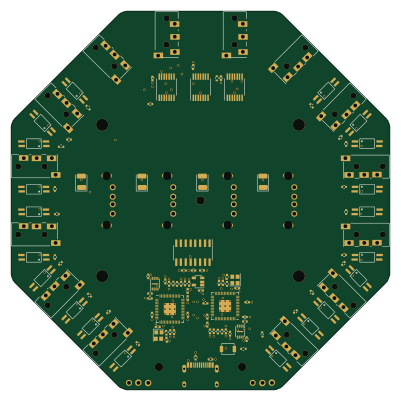 RP2040/RP2350
Hid remapper
jfedor2
100 × 100 mm124 parts2LMIT1.7k RP2040/RP2350
MSA
Mentra-Community
30.5 × 138 mm61 parts2LMIT1.2k RP2040/RP2350
Open Source Smart Glasses
93 × 10.5 mm80 parts4LMIT1.2k