
Redroid go

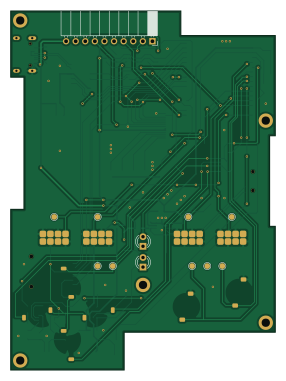
About the Redroid go PCB
Redroid go is an open source ESP32 PCB design by aseoista, published on GitHub under the GPL-3.0 license. It is a 2-layer board measuring 70 × 95 mm, with 80 components from 43 distinct parts.
Its main chip is the C529589, from the ESP32 family. Other key parts include the C84681, C3003189, C160463, C5252899 and C111196. By type, the board carries 25 resistors, 19 capacitors, 11 switches, 9 ICs, 4 connectors and 3 transistors.
It belongs with the retro computing designs in this gallery.
From the project
Open ESP32-based gaming handheld inspired by the original ODROID-GO
REDROID-GO is an open-source, custom-designed handheld gaming console inspired by the original ODROID-GO. This project enhances the original (discontinued) design with modern features, while maintaining as much as possible software compatibility.
Tips - A regular soldering iron is sufficient — use a thin tip for finer control - Apply no-clean flux or thermal flux to ease solder flow and avoid bridges - Start with the USB-C connector and the display connector — they are the most difficult parts to solder; then proceed with the remaining components - A desoldering braid can be very useful to…
Main components on the Redroid go
Redroid go bill of materials (BOM)
80 components, 43 distinct parts — part numbers from the project's BOM.
| Qty | Part | Footprint | Refs |
|---|---|---|---|
| 1 | C529589 ESP32-WROVER-E-N16R8 | ESP32-WROVER-E_EXP | U1 |
| 1 | C84681 CH340C | SOIC-16_3.9x9.9mm_P1.27mm | U2 |
| 1 | C3003189 MP2161GJ-Z | TSOT23-8_MP2161_MNP | U3 |
| 1 | C160463 XC6802A42XMR-G | SOP_XC6802_TOR | U4 |
| 1 | C5252899 XC6206PxxxMR | SOT-23-3 | U5 |
| 1 | C111196 uSD | SOFNG_TF-15x15 | U6 |
| 3 | C7420 NC7SZ125M5X | SOT-23-5_HandSoldering | U7, U8, U9 |
| 2 | C62892 UMH3N | SOT-363_SC-70-6_Handsoldering | Q1, Q3 |
| 1 | C7422949 PMOS | SOT-23 | Q2 |
| 1 | C136423 USB4105-GF-A | GCT_USB4105-GF-A | J1 |
| 1 | C3249996 5051101892 | CON_5051101892_MOL | J2 |
| 1 | C3029359 Conn_01x02_Pin | JST_GH_SM02B-GHS-TB_1x02-1MP_P1.25mm_Horizontal | J3 |
| 1 | C2897392 Conn_01x10_Pin | PinSocket_1x10_P2.54mm_Horizontal | J4 |
| 1 | C3029359 Battery_Cell | JST_GH_SM02B-GHS-TB_1x02-1MP_P1.25mm_Horizontal | BT1 |
| 1 | C41380232 Fuse | Fuse_0603_1608Metric | F1 |
| 1 | C581342 PAM8304 | MSOP-8_3x3mm_P0.65mm | PAM8304 |
| 1 | UP | CONDUCTIVE_BUTTON_DIRECTIONAL_THICK | SW1 |
| 1 | DOWN | CONDUCTIVE_BUTTON_DIRECTIONAL_THICK | SW2 |
| 1 | LEFT | CONDUCTIVE_BUTTON_DIRECTIONAL_THICK | SW3 |
| 1 | RIGHT | CONDUCTIVE_BUTTON_DIRECTIONAL_THICK | SW4 |
Show 23 more
| Qty | Part | Footprint | Refs |
|---|---|---|---|
| 1 | MENU | CONDUCTIVE_BUTTON_THICK_STARTSELECT | SW5 |
| 1 | VOLUME | CONDUCTIVE_BUTTON_THICK_STARTSELECT | SW6 |
| 1 | SELECT | CONDUCTIVE_BUTTON_THICK_STARTSELECT | SW7 |
| 1 | START | CONDUCTIVE_BUTTON_THICK_STARTSELECT | SW8 |
| 1 | B | CONDUCTIVE_BUTTON | SW9 |
| 1 | A | CONDUCTIVE_BUTTON | SW10 |
| 1 | C963208 SW_SPDT | MK-12F03-G015 | SW11 |
| 1 | C42441798 D_Schottky | Nexperia_CFP3_SOD-123W | D1 |
| 2 | LED | LED_D3.0mm | D2, D3 |
| 2 | C19330 FerriteBead | L_0603_1608Metric_Pad1.05x0.95mm_HandSolder | FB1, FB2 |
| 1 | C598616 1uH | L_Murata_LQH2MCNxxxx02_2.0x1.6mm | L1 |
| 10 | C14663 0.1uF | C_0603_1608Metric_Pad1.08x0.95mm_HandSolder | C1, C2, C6, C8, C9, C10, C11, C12 +2 |
| 2 | C159801 22uF | C_0603_1608Metric_Pad1.08x0.95mm_HandSolder | C3, C7 |
| 3 | C19702 10uF | C_0603_1608Metric_Pad1.08x0.95mm_HandSolder | C4, C5, C16 |
| 2 | C107081 220pF | C_0603_1608Metric_Pad1.08x0.95mm_HandSolder | C14, C15 |
| 2 | C15849 1uF | C_0603_1608Metric_Pad1.08x0.95mm_HandSolder | C17, C18 |
| 2 | C881139 5.1k | R_0603_1608Metric_Pad0.98x0.95mm_HandSolder | R1, R2 |
| 9 | C14675 100k | R_0603_1608Metric_Pad0.98x0.95mm_HandSolder | R3, R9, R10, R11, R12, R13, R14, R22 +1 |
| 1 | C49965 200k | R_0603_1608Metric_Pad0.98x0.95mm_HandSolder | R4 |
| 1 | C2930103 44k2 | R_0603_1608Metric_Pad0.98x0.95mm_HandSolder | R5 |
| 3 | C2907137 2k | R_0603_1608Metric_Pad0.98x0.95mm_HandSolder | R6, R8, R18 |
| 5 | C98220 10k | R_0603_1608Metric_Pad0.98x0.95mm_HandSolder | R7, R15, R16, R17, R20 |
| 4 | C403071 21R | R_0603_1608Metric_Pad0.98x0.95mm_HandSolder | R19, R24, R25, R26 |
Redroid go design files
The KiCad project lives in the aseoista/redroid-go repository on GitHub; these links point at the commit this page was built from.
- Layoutpcb/redroid_go.kicad_pcb
- Schematicpcb/redroid_go.kicad_sch
- BOMBOM_redroid_go_LCSC.csv
Redroid go: common questions
What microcontroller does the Redroid go use?
The Redroid go is built around the C529589, from the ESP32 family.
How big is the Redroid go PCB?
The Redroid go measures 70 × 95 mm, has 2 copper layers and is 1.6 mm thick.
How many components are on the Redroid go?
80 components, from 43 distinct parts, with part numbers taken from the project's own BOM. The full bill of materials is listed on this page.
Where can I download the Redroid go design files?
From the aseoista/redroid-go repository on GitHub, which has the KiCad layout, the schematic and the BOM; the links under Design files point to each one.
Can I use the Redroid go design in my own project?
Yes, under the terms of its GPL-3.0 license, which aseoista chose for the repository.
Can I test firmware for the Redroid go without the hardware?
Yes. HardLabs builds a simulation of the board from its netlist and BOM, so you can run and debug ESP32 firmware against it before you order a PCB.
Similar boards
 ESP32
OSO-BOOK-B1
joeycastillo
85 × 115 mm65 parts2LCC-BY-SA-4.08.1k ESP32
Powertrain
byrantech
64 × 45.4 mm171 parts4LMIT4.3k ESP32
Esp32 minimal
atopile
36.2 × 26.8 mm20 parts2LMIT4.0k ESP32
Badge
56.3 × 39 mm239 parts4LMIT4.0k ESP32
Racer
StuckAtPrototype
36 × 50.2 mm70 parts4LApache-2.03.8k ESP32
Controller
29 × 74 mm58 parts4LApache-2.03.8k