
VikramSat-RF-subsystem


About the VikramSat-RF-subsystem PCB
VikramSat-RF-subsystem is an open source RP2040/RP2350 PCB design by Astralis1409, published on GitHub under the MIT license. It is a 4-layer board measuring 72 × 72 mm, with 89 components from 38 distinct parts.
Its main chip is the RP2350A-QFN60, from the RP2040/RP2350 family. Other key parts include the CC1125RHBR, BALF-SPI2-02D3, 4259-63, W25Q128JVS and GSQ5110. By type, the board carries 49 capacitors, 14 resistors, 9 ICs, 4 connectors, 4 diodes and 2 crystals.
It belongs with the rf & radio designs in this gallery.
From the project
WIP - VikramSat's Official Radio Communications Subsystem with hardware, software and more.
The RF transmitter on this board has an output Power of 4 Watts and it is not recommend to use this without a ham radio license. although you can receive data just fine.
It uses the CC1125 RF Transceiver from Texas Instruments as it's Transceiver and GSQ5111 Power Amplifier and it operates in the 70cm band. the RP2350A acts as a control IC for the CC1125 and this simplifies the process for the OnBoard Computer(the OBC of the cubesat)
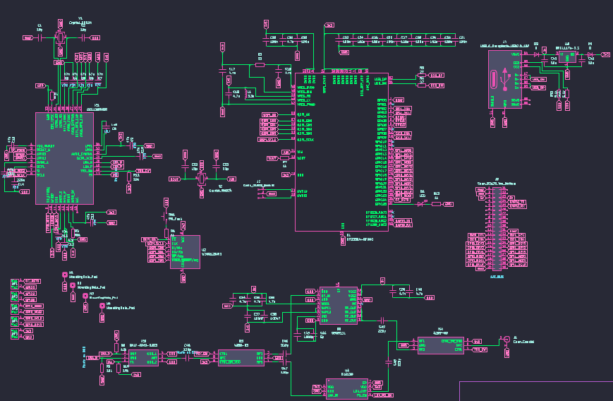
Main components on the VikramSat-RF-subsystem
VikramSat-RF-subsystem bill of materials (BOM)
89 components, 38 distinct parts — part numbers from the project's BOM.
| Qty | Part | Footprint | Refs |
|---|---|---|---|
| 1 | CC1125RHBR | QFN50P500X500X100-33N-D | IC1 |
| 1 | BALF-SPI2-02D3 | BALFSPI202D3 | IC2 |
| 2 | 4259-63 | PE4259 | IC3, IC4 |
| 1 | RP2350A-QFN60 | RP2350A_QFN-60_EP_7.75x7.75_Pitch0.4mm | U1 |
| 1 | W25Q128JVS | SOIC-8_5.3x5.3mm_P1.27mm | U2 |
| 1 | GSQ5110 | QFN-16_L3.0-W3.0-P0.50-TL-EP2.0 | U3 |
| 1 | SK5129 | DFN-6_L1.6-W1.6-P0.50-BL-EP1.0 | U4 |
| 1 | AMS1117S-3.3 AMS1117s-3.3 | SOT-89-3 | U5 |
| 2 | CRYSTAL_GND24 Crystal_GND24 | Crystal_SMD_3225-4Pin_3.2x2.5mm | Y1, Y2 |
| 1 | Conn_Coaxial | SMA_Amphenol_901-143_Horizontal | J1 |
| 1 | CONN_01X03_SOCKET Conn_01x03_Socket | PinHeader_1x03_P2.54mm_Vertical | J2 |
| 1 | CONN_02X20_TOP_BOTTOM Conn_02x20_Top_Bottom | PinHeader_2x20_P2.54mm_Vertical | J3 |
| 1 | USB_C_RECEPTACLE_USB2.0_16P USB_C_Receptacle_USB2.0_16P | USB_C_Receptacle_XKB_U262-16XN-4BVC11 | J4 |
| 5 | ~ | Debug Pad | DP1, DP2, DP3, DP4, DP5 |
| 1 | SW_Push | SW_SPST_PTS810 | SW1 |
| 1 | LED | LED_0402_1005Metric | D1 |
| 2 | D | D_0402_1005Metric | D2, D3 |
| 1 | ESDS314DBVR | ESDS314BVR_SOT95P280X145-5N | D4 |
| 1 | 3.3U 3.3u | IND-SMD_L2.0-W1.6_AOTA-B201610S3R3-101-T | L1 |
| 4 | 15P 15p | C_0402_1005Metric | C1, C2, C32, C33 |
Show 18 more
| Qty | Part | Footprint | Refs |
|---|---|---|---|
| 11 | 47N 47n | C_0402_1005Metric | C3, C4, C5, C6, C7, C9, C11, C12 +3 |
| 1 | 1N8 1n8 | C_0402_1005Metric | C8 |
| 1 | 10N 10n | C_0402_1005Metric | C10 |
| 1 | 220N 220n | C_0402_1005Metric | C14 |
| 9 | 4.7U 4.7u | C_0402_1005Metric | C17, C18, C19, C21, C34, C35, C36, C39 +1 |
| 11 | 100N 100n | C_0402_1005Metric | C20, C22, C23, C24, C25, C26, C27, C28 +3 |
| 2 | 100NF 100nF | C_0402_1005Metric | C37, C38 |
| 2 | 10U 10u | C_0805_2012Metric | C41, C42 |
| 1 | 1200P 1200p | C_0402_1005Metric | C43 |
| 1 | 5p | C_0402_1005Metric | C44 |
| 5 | 220P 220p | C_0402_1005Metric | C45, C46, C47, C48, C49 |
| 1 | 0 | R_0402_1005Metric | R1 |
| 1 | 56K 56k | R_0402_1005Metric | R2 |
| 1 | 33 | R_0402_1005Metric | R3 |
| 2 | 27 | R_0402_1005Metric | R4, R5 |
| 3 | 1k | R_0402_1005Metric | R6, R7, R12 |
| 4 | 10K 10k | R_0402_1005Metric | R8, R9, R10, R11 |
| 2 | 5.1K 5.1k | R_0402_1005Metric | R13, R14 |
VikramSat-RF-subsystem design files
The KiCad project lives in the Astralis1409/VikramSat-RF-subsystem repository on GitHub; these links point at the commit this page was built from.
VikramSat-RF-subsystem: common questions
What microcontroller does the VikramSat-RF-subsystem use?
The VikramSat-RF-subsystem is built around the RP2350A-QFN60, from the RP2040/RP2350 family.
How big is the VikramSat-RF-subsystem PCB?
The VikramSat-RF-subsystem measures 72 × 72 mm, has 4 copper layers and is 1.6 mm thick.
How many components are on the VikramSat-RF-subsystem?
89 components, from 38 distinct parts, with part numbers taken from the project's own BOM. The full bill of materials is listed on this page.
Where can I download the VikramSat-RF-subsystem design files?
From the Astralis1409/VikramSat-RF-subsystem repository on GitHub, which has the KiCad layout, the schematic and the BOM; the links under Design files point to each one.
Can I use the VikramSat-RF-subsystem design in my own project?
Yes, under the terms of its MIT license, which Astralis1409 chose for the repository.
Can I test firmware for the VikramSat-RF-subsystem without the hardware?
Yes. HardLabs builds a simulation of the board from its netlist and BOM, so you can run and debug RP2040/RP2350 firmware against it before you order a PCB.
Similar boards
 RP2040/RP2350
Open Book Abridged Edition
joeycastillo
85 × 115 mm29 parts2LCC-BY-SA-4.08.1k RP2040/RP2350
Corne
foostan
277.2 × 107.5 mm164 parts2LCC-BY-4.07.7k RP2040/RP2350
Corne
277.2 × 107.5 mm164 parts2LCC-BY-4.07.7k RP2040/RP2350
Msa
Mentra-Community
47.8 × 9.4 mm53 parts2LMIT1.2k RP2040/RP2350
Open Source Smart Glasses
93 × 10.5 mm80 parts4LMIT1.2k RP2040/RP2350
MSA
30.5 × 138 mm61 parts2LMIT1.2k