
Ethernet

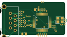
About the Ethernet PCB
Ethernet is an open source PCB design by atopile, published on GitHub under the MIT license. It is a 2-layer board measuring 33.2 × 17.3 mm, with 32 components from 26 distinct parts.
Other key parts include the C2913205, C139797 and C709357. By type, the board carries 16 capacitors, 13 resistors and 3 ICs.
It belongs with the power & battery designs in this gallery.
From the project
This cell-sim is designed to mimic a LiPo battery pack for develpoment of the surrounding electronics, like a BMS.
This cell-sim is designed to mimic a LiPo battery pack for develpoment of the surrounding electronics, like a BMS.
- 16 channels - Open-Source hardware design, you can embed onto your own HIL setup - ⚡️ 0-4.5V and 0-500mA per channel - DMM muxed to each channel for arbitarily precise measurment - Open-circuit simulation on each channel - 📏 16bit ADC feedback for voltage and current - 🔌 USB w/ Python software interface (+ 100MBit Ethernet + WiFi waiting for firmware support)
Main components on the Ethernet
Ethernet bill of materials (BOM)
32 components, 26 distinct parts — part numbers from the project's BOM.
| Qty | Part | Footprint | Refs |
|---|---|---|---|
| 1 | C2913205 ? | LQFP-48_L7.0-W7.0-P0.50-LS9.0-BL | U1 |
| 1 | C139797 ? | RJ45-TH_J1B1211CCD | U2 |
| 1 | C709357 ? | CRYSTAL-SMD_4P-L3.2-W2.5-BL | U3 |
| 1 | C1525 50V 1nF X7R ±10% 0805 Multilayer Ceramic Capacitors MLCC - SMD/SMT ROHS | C0805 | C1 |
| 1 | C15850 50V 22nF X7R ±10% 0402 Multilayer Ceramic Capacitors MLCC - SMD/SMT ROHS | C0402 | C2 |
| 1 | C15850 50V 6.8nF X7R ±10% 0402 Multilayer Ceramic Capacitors MLCC - SMD/SMT ROHS | C0402 | C3 |
| 1 | C46653 50V 6.8nF X7R ±10% 0402 Multilayer Ceramic Capacitors MLCC - SMD/SMT ROHS | C0402 | C4 |
| 1 | C1532 50V 10nF X7R ±10% 0402 Multilayer Ceramic Capacitors MLCC - SMD/SMT ROHS | C0402 | C5 |
| 1 | C93654 50V 10nF X7R ±10% 0402 Multilayer Ceramic Capacitors MLCC - SMD/SMT ROHS | C0402 | C6 |
| 1 | C93654 10V 4.7uF X5R ±20% 0402 Multilayer Ceramic Capacitors MLCC - SMD/SMT ROHS | C0402 | C7 |
| 2 | C15195 16V 100nF X7R ±10% 0402 Multilayer Ceramic Capacitors MLCC - SMD/SMT ROHS | C0402 | C8, C9 |
| 1 | C23733 16V 100nF X7R ±10% 0402 Multilayer Ceramic Capacitors MLCC - SMD/SMT ROHS | C0402 | C10 |
| 3 | C1525 16V 100nF X7R ±10% 0402 Multilayer Ceramic Capacitors MLCC - SMD/SMT ROHS | C0402 | C11, C12, C13 |
| 1 | C1525 25V 10uF X5R ±10% 0805 Multilayer Ceramic Capacitors MLCC - SMD/SMT ROHS | C0805 | C14 |
| 2 | C1525 50V 10pF C0G ±5% 0402 Multilayer Ceramic Capacitors MLCC - SMD/SMT ROHS | C0402 | C15, C16 |
| 1 | C25744 62.5mW Thick Film Resistors 50V ±100ppm/℃ ±1% 200Ω 0402 Chip Resistor - Surface Mount ROHS | R0402 | R1 |
| 1 | C25905 62.5mW Thick Film Resistors 50V ±100ppm/℃ ±1% 200Ω 0402 Chip Resistor - Surface Mount ROHS | R0402 | R2 |
| 1 | C25905 62.5mW Thick Film Resistors 50V ±100ppm/℃ ±1% 33Ω 0402 Chip Resistor - Surface Mount ROHS | R0402 | R3 |
| 1 | C25087 62.5mW Thick Film Resistors 50V ±100ppm/℃ ±1% 33Ω 0402 Chip Resistor - Surface Mount ROHS | R0402 | R4 |
| 1 | C25087 62.5mW Thick Film Resistors 50V ±100ppm/℃ ±1% 49.9Ω 0402 Chip Resistor - Surface Mount ROHS | R0402 | R5 |
Show 6 more
| Qty | Part | Footprint | Refs |
|---|---|---|---|
| 2 | C25105 62.5mW Thick Film Resistors 50V ±100ppm/℃ ±1% 49.9Ω 0402 Chip Resistor - Surface Mount ROHS | R0402 | R6, R11 |
| 1 | C25105 62.5mW Thick Film Resistors 50V ±1% ±200ppm/℃ 10Ω 0402 Chip Resistor - Surface Mount ROHS | R0402 | R7 |
| 2 | C25120 62.5mW Thick Film Resistors 50V ±100ppm/℃ ±1% 33Ω 0402 Chip Resistor - Surface Mount ROHS | R0402 | R8, R9 |
| 1 | C25077 62.5mW Thick Film Resistors 50V ±100ppm/℃ ±1% 49.9Ω 0402 Chip Resistor - Surface Mount ROHS | R0402 | R10 |
| 1 | C25105 62.5mW Thick Film Resistors 50V ±100ppm/℃ ±1% 12.4kΩ 0402 Chip Resistor - Surface Mount ROHS | R0402 | R12 |
| 1 | C25120 62.5mW Thick Film Resistors 50V ±100ppm/℃ ±1% 1MΩ 0402 Chip Resistor - Surface Mount ROHS | R0402 | R13 |
Ethernet design files
The KiCad project lives in the atopile/cell-sim repository on GitHub; these links point at the commit this page was built from.
Ethernet: common questions
How big is the Ethernet PCB?
The Ethernet measures 33.2 × 17.3 mm, has 2 copper layers and is 1.6 mm thick.
How many components are on the Ethernet?
32 components, from 26 distinct parts, with part numbers taken from the project's own BOM. The full bill of materials is listed on this page.
Where can I download the Ethernet design files?
From the atopile/cell-sim repository on GitHub, which has the KiCad layout, the schematic and the BOM; the links under Design files point to each one.
Can I use the Ethernet design in my own project?
Yes, under the terms of its MIT license, which atopile chose for the repository.
More boards in cell-sim
Cell sim
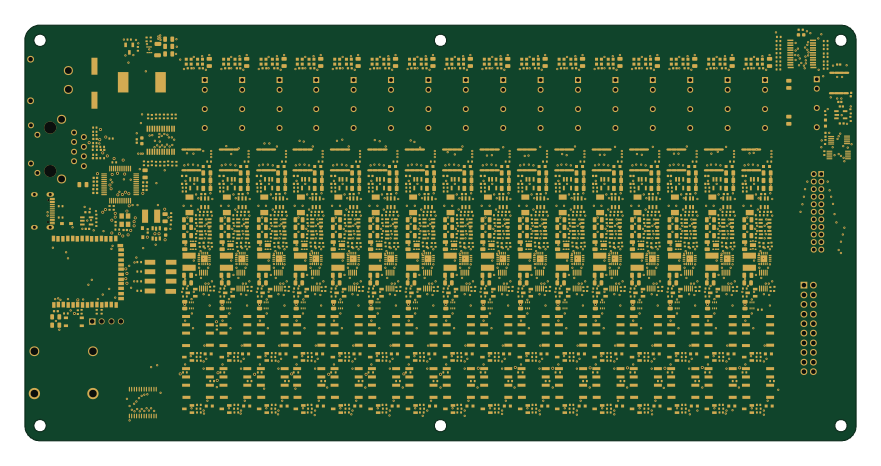
220 × 110 mm1152 parts4LMIT24
Cell
92.9 × 7.9 mm63 parts4LMIT24
Tca9548apwr
10.5 × 12.4 mm20 parts2LMIT24
Lv2842xlvddcr
72.3 × 100.8 mm8 parts2LMIT24
Saleae header
72.3 × 100.8 mm5 parts2LMIT24
Ldk220m r
72.3 × 100.8 mm5 parts2LMIT24
Bq24045dsqr
72.3 × 100.8 mm4 parts2LMIT24
Level shifter
72.3 × 100.8 mm3 parts2LMIT24
Usbc
72.3 × 100.8 mm3 parts2LMIT24
Similar boards

EinkPDA screen
TalismanDesign
95 × 54 mm27 parts2LApache-2.02.0k
Stack chan
stack-chan
50 × 50 mm33 parts2LApache-2.01.7k
Display Carrier
AxxAxx
35.6 × 58.2 mm5 parts2LGPL-3.01.7k
ProgrammingAdapter
stuartpittaway
10.5 × 83 mm3 parts2LCC-BY-NC-4.01.1k
TemperaturePCB PANEL
116 × 75.5 mm178 parts2LCC-BY-NC-4.01.1k
Module 16S PassiveBalanceAddOn
61 × 74 mm86 parts2LCC-BY-NC-4.01.1k