
Backplane V1.1

About the Backplane V1.1 PCB
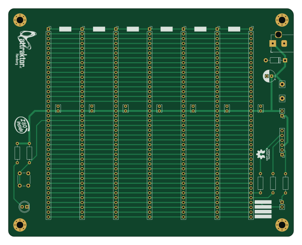
Backplane V1.1 is an open source PCB design by attraktorhh, published on GitHub under the MIT license. It is a 2-layer board measuring 150 × 120 mm, with 29 components from 16 distinct parts.
By type, the board carries 8 capacitors, 5 resistors, 4 connectors, 2 jumpers, 2 diodes and 1 switch.
From the project
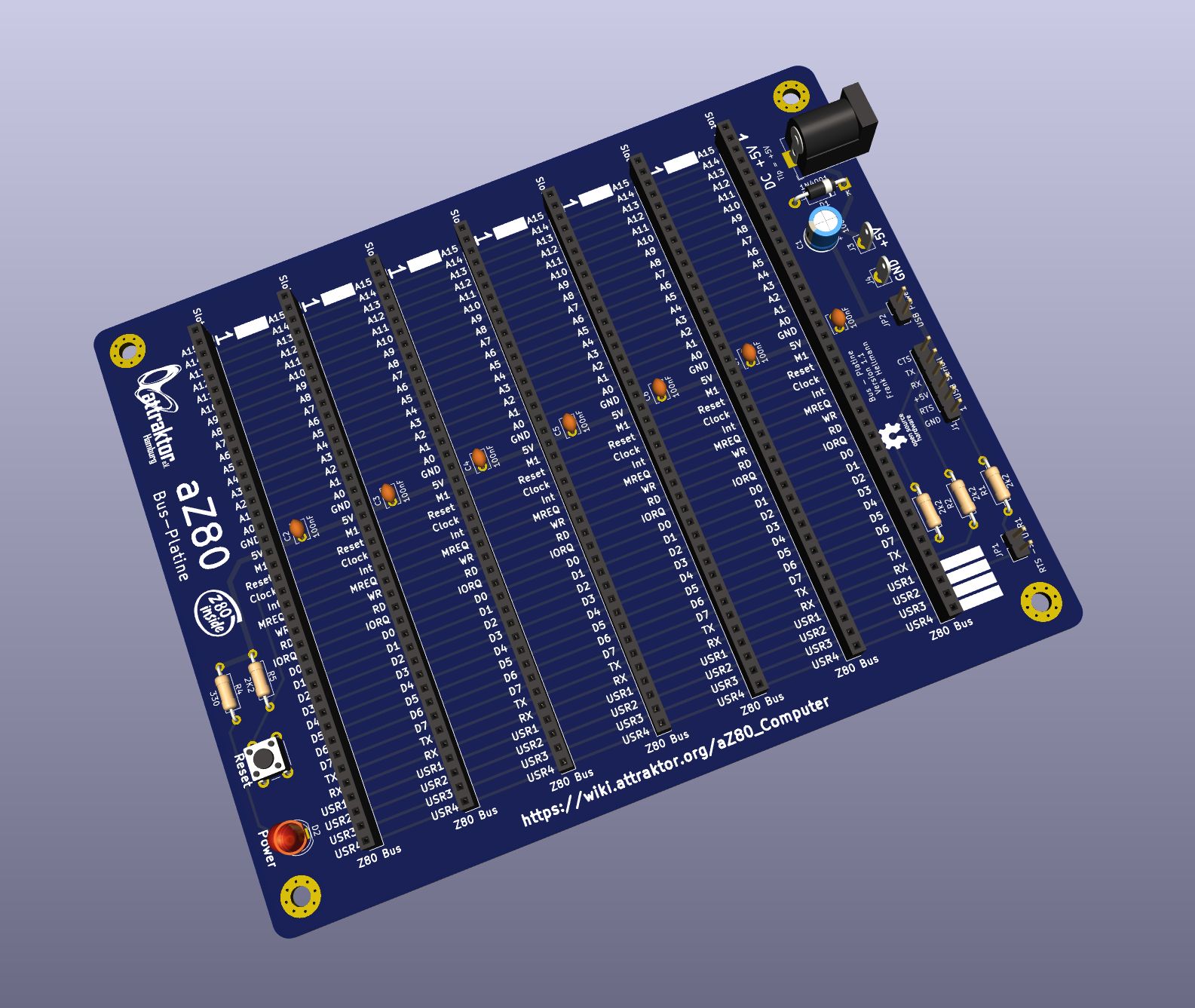
Die Bus-Platine bildet das Rückgrat unseres Computers. Sie verbindet die einzelnen Karten des aZ80 miteinander.
Die Bus-Platine bildet das Rückgrat unseres Computers. Sie verbindet die einzelnen Karten des aZ80 miteinander.
Die sieben Slots sind alle gleich belegt und leiten den Adress- und Datenbus sowie die Kontrollsignale und die Versorgungsspannung weiter an die verschiedenen Karten.
Die LED D2 zeigt an, dass eine Versorgungsspannung anliegt.
Der Taster SW1 erlaubt das Zurücksetzen und Neustarten des Computers, der sogenannte RESET. Dies ist hilfreich, wenn der aZ80 mal nicht mehr reagieren sollte.
Backplane V1.1 bill of materials (BOM)
29 components, 16 distinct parts — part numbers from the project's BOM.
| Qty | Part | Footprint | Refs |
|---|---|---|---|
| 1 | USB Seriell | PinHeader_1x06_P2.54mm_Vertical | J1 |
| 1 | C22750565 DC +5V | BarrelJack_Horizontal | J2 |
| 1 | +5V Hook | Pin_D1.3mm_L10.0mm_W3.5mm_Flat | J3 |
| 1 | GND Hook | Pin_D1.3mm_L10.0mm_W3.5mm_Flat | J4 |
| 1 | RTS -> USR1 | PinHeader_1x02_P2.54mm_Vertical | JP1 |
| 1 | 5V USB | PinHeader_1x02_P2.54mm_Vertical | JP2 |
| 1 | C221872 Reset | SW_PUSH_6mm | SW1 |
| 7 | Z80 Bus | PinSocket_1x40_P2.54mm_Vertical | Slot 1, Slot 2, Slot 3, Slot 4, Slot 5, Slot 6, Slot 7 |
| 1 | SS14 1N4001 | D_DO-41_SOD81_P10.16mm_Horizontal | D1 |
| 1 | Power | LED_D5.0mm | D2 |
| 1 | 10UF 100uF | CP_Radial_D6.3mm_P2.50mm | C1 |
| 7 | 100nF | C_Disc_D3.8mm_W2.6mm_P2.50mm | C2, C3, C4, C5, C6, C7, C8 |
| 1 | 10K 2k2 | R_Axial_DIN0207_L6.3mm_D2.5mm_P10.16mm_Horizontal | R1 |
| 1 | 22K 2k2 | R_Axial_DIN0207_L6.3mm_D2.5mm_P10.16mm_Horizontal | R2 |
| 2 | 2k2 | R_Axial_DIN0207_L6.3mm_D2.5mm_P10.16mm_Horizontal | R3, R5 |
| 1 | 330 | R_Axial_DIN0207_L6.3mm_D2.5mm_P10.16mm_Horizontal | R4 |
Backplane V1.1 design files
The KiCad project lives in the attraktorhh/aZ80_Computer repository on GitHub; these links point at the commit this page was built from.
Backplane V1.1: common questions
How big is the Backplane V1.1 PCB?
The Backplane V1.1 measures 150 × 120 mm, has 2 copper layers and is 1.6 mm thick.
How many components are on the Backplane V1.1?
29 components, from 16 distinct parts, with part numbers taken from the project's own BOM. The full bill of materials is listed on this page.
Where can I download the Backplane V1.1 design files?
From the attraktorhh/aZ80_Computer repository on GitHub, which has the KiCad layout, the schematic and the BOM; the links under Design files point to each one.
Can I use the Backplane V1.1 design in my own project?
Yes, under the terms of its MIT license, which attraktorhh chose for the repository.
More boards in aZ80_Computer
AZ80 DIO
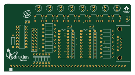
110.3 × 58.3 mm49 parts2LMIT4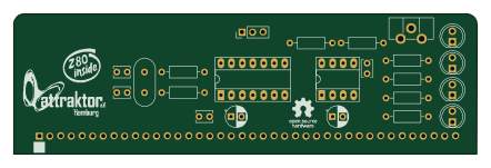
AZ80 Clock
110.3 × 33.3 mm24 parts2LMIT4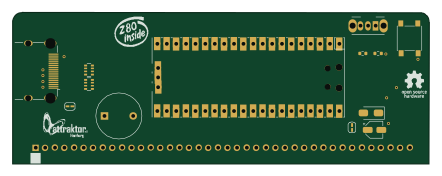 RP2040/RP2350
AZ80 VDP
110.3 × 40 mm12 parts2LMIT4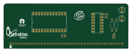
AZ80 SIO
110.3 × 40 mm10 parts2LMIT4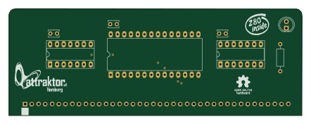
AZ80 RAM
110.3 × 40 mm9 parts2LMIT4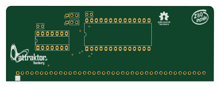
AZ80 ROM
110.3 × 40 mm7 parts2LMIT4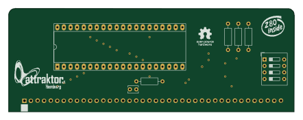
AZ80 CPU
110.3 × 40 mm7 parts2LMIT4