
Ir sensor strobe

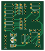
About the Ir sensor strobe PCB
Ir sensor strobe is an open source PCB design by bburan, published on GitHub. It is a 2-layer board measuring 37.5 × 43.5 mm, with 27 components from 17 distinct parts.
Other key parts include the TLC555CP. By type, the board carries 12 resistors, 8 connectors, 5 capacitors, 1 IC and 1 transistor.
It belongs with the sensors designs in this gallery.
From the project
A small four‑channel infrared emitter/detector board. Four IR LEDs (OP140) are driven as a single strobed array; four phototransistors (OP550) act as independent detectors, each presenting an analog output to a downstream acquisition system.
A small four‑channel infrared emitter/detector board. Four IR LEDs (OP140) are driven as a single strobed array; four phototransistors (OP550) act as independent detectors, each presenting an analog output to a downstream acquisition system.
The strobe carrier can come from either an on‑board ~500 Hz oscillator or an external control signal, selected by a jumper at J1. The optoelectronics mount remotely and connect through headers. The board is all through‑hole and is intended to be hand‑soldered.
Main components on the Ir sensor strobe
Ir sensor strobe bill of materials (BOM)
27 components, 17 distinct parts.
| Qty | Part | Footprint | Refs |
|---|---|---|---|
| 1 | TLC555CP | DIP-8_W7.62mm | U1 |
| 1 | 2N4401 | TO-92_Inline_Wide | Q1 |
| 1 | CTL select | PinHeader_1x03_P2.54mm_Vertical | J1 |
| 1 | Sensors | PinHeader_1x04_P2.54mm_Vertical | J2 |
| 1 | Conn_01x05 | PinHeader_1x05_P2.54mm_Vertical | J3 |
| 1 | Conn_01x02 | PinHeader_1x02_P2.54mm_Vertical | J4 |
| 1 | OP550 return | PinHeader_1x04_P2.54mm_Vertical | J5 |
| 1 | OP550 out | PinHeader_1x04_P2.54mm_Vertical | J6 |
| 1 | OP140 in | PinHeader_1x04_P2.54mm_Vertical | J7 |
| 1 | OP140 out | PinHeader_1x04_P2.54mm_Vertical | J8 |
| 1 | 10 uF | CP_Radial_D5.0mm_P2.50mm | C1 |
| 3 | 0.1 uF | C_Disc_D5.0mm_W2.5mm_P2.50mm | C2, C3, C5 |
| 1 | 0.01 uF | C_Disc_D5.0mm_W2.5mm_P2.50mm | C4 |
| 2 | 1k | R_Axial_DIN0207_L6.3mm_D2.5mm_P7.62mm_Horizontal | R1, R11 |
| 4 | 68 | R_Axial_DIN0207_L6.3mm_D2.5mm_P7.62mm_Horizontal | R2, R3, R4, R5 |
| 5 | 10k | R_Axial_DIN0207_L6.3mm_D2.5mm_P7.62mm_Horizontal | R6, R7, R8, R9, R10 |
| 1 | 14k | R_Axial_DIN0207_L6.3mm_D2.5mm_P7.62mm_Horizontal | R12 |
Ir sensor strobe design files
The KiCad project lives in the bburan/ir-sensor-strobe repository on GitHub; these links point at the commit this page was built from.
- LayoutIR sensor strobe.kicad_pcb
- SchematicIR sensor strobe.kicad_sch
Ir sensor strobe: common questions
How big is the Ir sensor strobe PCB?
The Ir sensor strobe measures 37.5 × 43.5 mm, has 2 copper layers and is 1.6 mm thick.
How many components are on the Ir sensor strobe?
27 components, from 17 distinct parts. The full bill of materials is listed on this page.
Where can I download the Ir sensor strobe design files?
From the bburan/ir-sensor-strobe repository on GitHub, which has the KiCad layout and the schematic; the links under Design files point to each one.
Can I use the Ir sensor strobe design in my own project?
The repository has no license, so all rights stay with bburan. Use it as a reference, and ask the author before reusing the design.
Similar boards

Sensor smd
scottbez1
40 × 20 mm5 parts2LApache-2.04.2k
Sensors
StuckAtPrototype
15.2 × 9 mm14 parts4LApache-2.03.8k
Microphone
Mentra-Community
5.5 × 6.1 mm6 parts2LMIT1.2k
TemperaturePCB PANEL
stuartpittaway
116 × 75.5 mm178 parts2LCC-BY-NC-4.01.1k
Pots
shanteacontrols
390 × 93 mm75 parts2LApache-2.0956
ButtonsLEDs
390 × 37 mm82 parts2LApache-2.0956