
ILV2-7-5 VFD Display

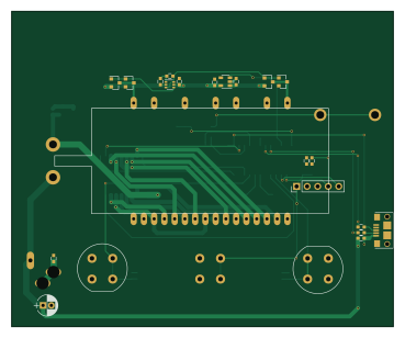
About the ILV2-7-5 VFD Display PCB
ILV2-7-5 VFD Display is an open source PIC PCB design by biomurph, published on GitHub under the GPL-3.0 license. It is a 2-layer board measuring 92 × 76 mm, with 50 components from 27 distinct parts.
Its main chip is the PIC32MX250F128B, from the PIC family. Other key parts include the DS3231M, 74HC2G14, TLV76033DBZR, MAX6920 and TC1014-2.5VCT713. By type, the board carries 17 capacitors, 10 resistors, 6 ICs, 4 transistors, 4 switches and 3 connectors.
It belongs with the displays & leds and power & battery designs in this gallery.
From the project
KiCAD circuit for a VFD Clock using the Popular ILV2-7/5 flat tube segmented nixie
This work is greatly indebted to work that came before. Namely Callum Nunez-Vas and his Dogbone Watch which is also based on the cyberpunk wristwatch by johngineer.
First, my uC is a PIC32MX250F128B, which supports USB OTG, which is nice and it's also Arduino compatible via ChipKIT and Digilent's DP32 which makes it nice for sharing.
The other thing that I changed is the oscillator that Callum used to drive the Cathode filament. Callum drives it with a timer on his PIC16F828. I needed more pins, so I decided to make a stand-alone relaxation oscillator built out of a 74HCG214 dual Schmidtt…
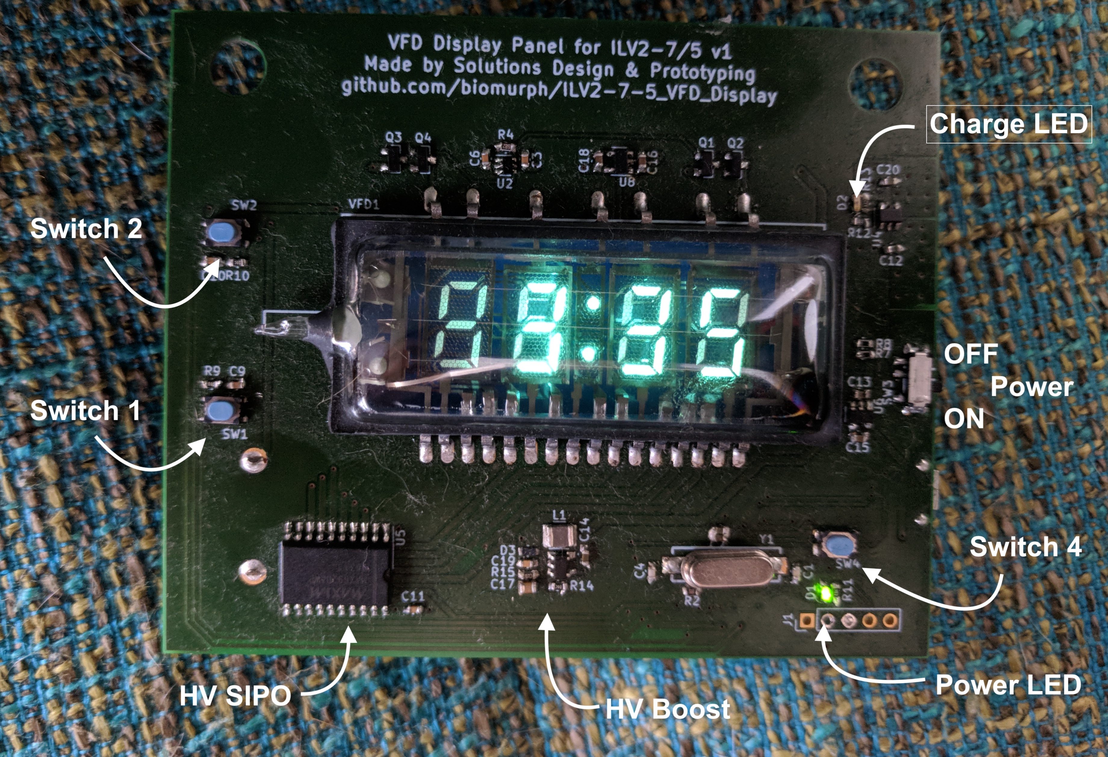
Main components on the ILV2-7-5 VFD Display
ILV2-7-5 VFD Display bill of materials (BOM)
50 components, 27 distinct parts.
| Qty | Part | Footprint | Refs |
|---|---|---|---|
| 1 | DS3231M | SOIC-8-N | U1 |
| 1 | 74HC2G14 | SOT-363_SC-70-6 | U2 |
| 1 | PIC32MX250F128B | SOIC-28 | U3 |
| 1 | TLV76033DBZR | SOT-23 | U4 |
| 1 | MAX6920 | SO-20_12.8x7.5mm_Pitch1.27mm | U5 |
| 1 | TC1014-2.5VCT713 | SOT-23-5 | U8 |
| 2 | BSS84 | SOT-23 | Q1, Q3 |
| 2 | BSS138 | SOT-23 | Q2, Q4 |
| 1 | 8MHz | TXC_5mmX2mm | Y1 |
| 1 | CONN_01X05 | Pin_Header_Straight_1x05_Pitch2.54mm | J1 |
| 1 | USB_OTG | 10118193_microUSB | J2 |
| 1 | BARREL_JACK | DC_PWR_PJ-006B | J3 |
| 1 | Battery_Cell | 12BH062-GR | BT1 |
| 3 | TACT_SWITCH | D6_SPST_SW | SW1, SW2, SW4 |
| 1 | GF-1123-1110 | SW_GF-1123-1110 | SW3 |
| 1 | ILV2-7/5 | IVL2-7-5 | VFD1 |
| 1 | LED | C_0603 | D1 |
| 2 | 500mA 30V | C_0603 | D2, D3 |
| 2 | 18pF | C_0603 | C1, C4 |
| 6 | 1uF | C_0603 | C2, C13, C15, C16, C18, C21 |
Show 7 more
| Qty | Part | Footprint | Refs |
|---|---|---|---|
| 6 | 0.1uF | C_0603 | C3, C5, C8, C9, C10, C11 |
| 1 | 0.15uF | C_0603 | C6 |
| 1 | 10uF | C_0603 | C7 |
| 1 | 4.7uF 50V | CP_Radial_D5.0mm_P2.00mm | C17 |
| 7 | 10k | C_0603 | R1, R3, R4, R5, R6, R9, R10 |
| 2 | 22R | C_0603 | R7, R8 |
| 1 | 1k | C_0603 | R11 |
ILV2-7-5 VFD Display design files
The KiCad project lives in the biomurph/ILV2-7-5_VFD_Display repository on GitHub; these links point at the commit this page was built from.
ILV2-7-5 VFD Display: common questions
What microcontroller does the ILV2-7-5 VFD Display use?
The ILV2-7-5 VFD Display is built around the PIC32MX250F128B, from the PIC family.
How big is the ILV2-7-5 VFD Display PCB?
The ILV2-7-5 VFD Display measures 92 × 76 mm, has 2 copper layers and is 1.6 mm thick.
How many components are on the ILV2-7-5 VFD Display?
50 components, from 27 distinct parts. The full bill of materials is listed on this page.
Where can I download the ILV2-7-5 VFD Display design files?
From the biomurph/ILV2-7-5_VFD_Display repository on GitHub, which has the KiCad layout; the links under Design files point to each one.
Can I use the ILV2-7-5 VFD Display design in my own project?
Yes, under the terms of its GPL-3.0 license, which biomurph chose for the repository.
Can I test firmware for the ILV2-7-5 VFD Display without the hardware?
Yes. HardLabs builds a simulation of the board from its netlist and BOM, so you can run and debug PIC firmware against it before you order a PCB.
Similar boards
 PIC
Pslab hardware
fossasia
99 × 53.3 mm187 parts4LApache-2.01.7k PIC
Lens
ervanalb
80 × 80 mm53 parts4LNo license515 PIC
Micro 8088
skiselev
152.4 × 101.6 mm71 partsGPL-3.0414 PIC
GB-CART256K-A
Gekkio
51.4 × 61 mm17 parts2LCC-BY-4.0379 PIC
GB-CARTPP-DIY
100 × 100 mm22 parts2LCC-BY-4.0379 PIC
GB-LIVE32
51.4 × 61 mm46 parts4LCC-BY-4.0379