
Afterglow 1.1

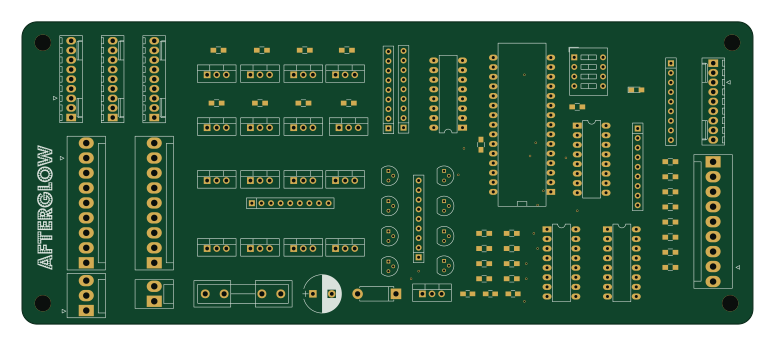
About the Afterglow 1.1 PCB
Afterglow 1.1 is an open source AVR/Arduino PCB design by bitfieldlabs, published on GitHub. It is a 2-layer board measuring 193.5 × 80 mm, with 78 components from 30 distinct parts.
Its main chip is the PC817, from the AVR/Arduino family. By type, the board carries 32 resistors, 24 transistors, 8 connectors, 6 ICs, 4 capacitors and 2 diodes.
It belongs with the retro computing designs in this gallery.
From the project
Pinball retro afterglow
AFTERGLOW is a pinball machine extension board that aims at softening the hard lamp on/off transitions which are the consequence of replacing the original incandescent bulbs with LEDs. Reproducing the original light effects is a big part of preserving a pinball game's nostalgia.
It currently works with Williams WPC, Williams System 11, Data East and probably also with Sega games. The basic principle involves resampling of the original lamp matrix signals at a higher frequency. This allows for PWM LED dimming with additional brightness steps.
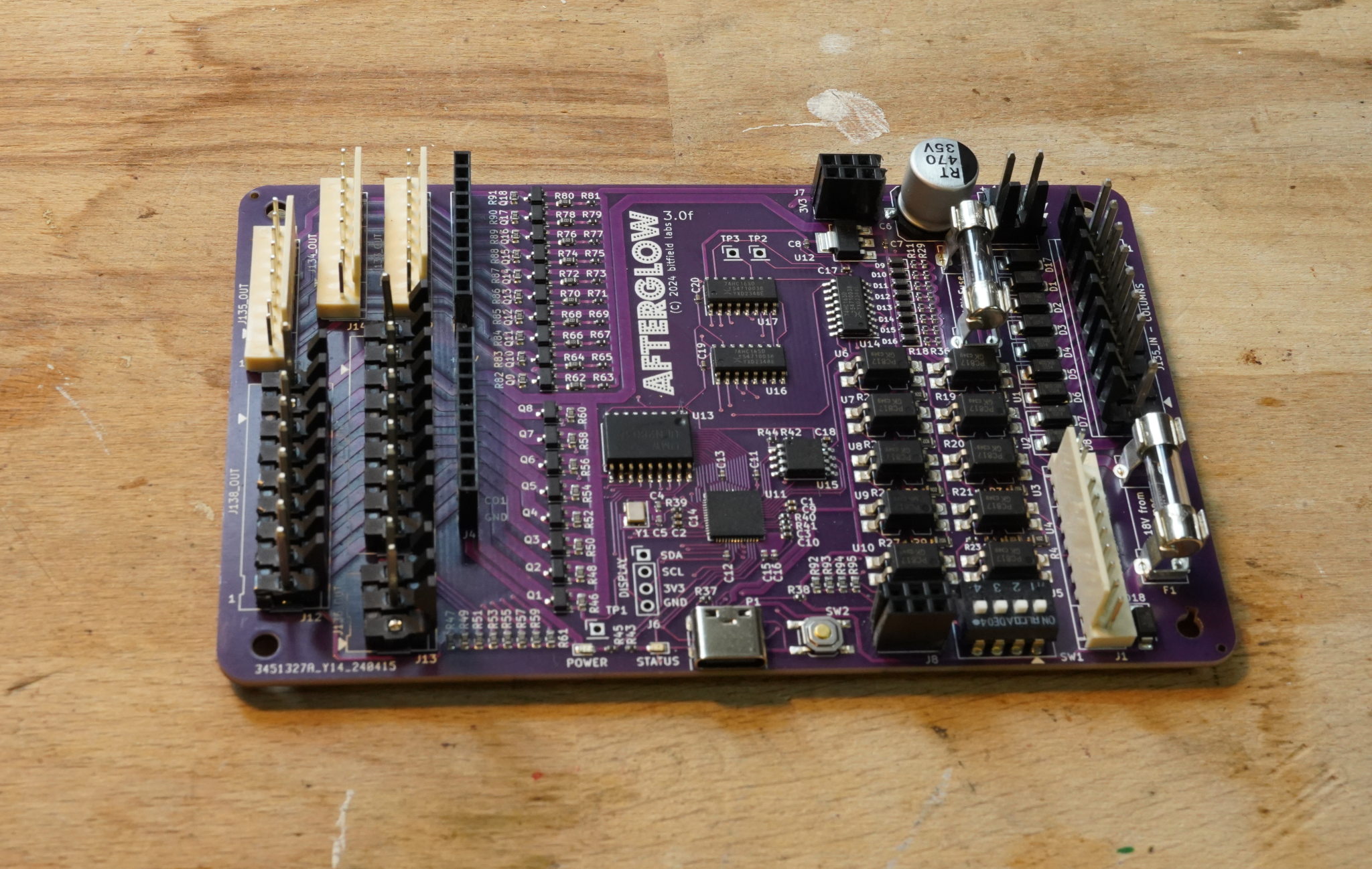
Main components on the Afterglow 1.1
Afterglow 1.1 bill of materials (BOM)
78 components, 30 distinct parts — part numbers from the project's BOM.
| Qty | Part | Footprint | Refs |
|---|---|---|---|
| 2 | PC817 74LS165 | DIP-16_W7.62mm_LongPads | U1, U2 |
| 1 | PC817 5V_Regulator | TO-220_Vertical | U3 |
| 1 | PC817 arduino nano | arduino_mini | U4 |
| 2 | PC817 74HC595 | DIP-16_W7.62mm_LongPads | U5, U6 |
| 8 | AO3401A 2N3904 | TO-92_Molded_Narrow | Q1, Q2, Q3, Q4, Q5, Q6, Q7, Q8 |
| 8 | AO3400A FQP27P06 | TO-220_Vertical | Q9, Q10, Q11, Q12, Q13, Q14, Q15, Q16 |
| 2 | AO3400A FQP30N06L | TO-220_Vertical | Q17, Q18 |
| 6 | FQP30N06L | TO-220_Vertical | Q19, Q20, Q21, Q22, Q23, Q24 |
| 1 | J133_IN_R | Molex_KK-6410-09_09x2.54mm_Straight | J34 IN |
| 1 | J137_IN_C | Molex_KK-41791-9_9x3.96mm_Straight | J38 IN |
| 1 | J133_OUT_R | Molex_KK-6410-09_09x2.54mm_Straight | J133 OUT |
| 1 | J134_OUT_R | Molex_KK-6410-09_09x2.54mm_Straight | J134 OUT |
| 1 | J135_OUT_R | Molex_KK-6410-09_09x2.54mm_Straight | J135 OUT |
| 1 | 136_OUT_C | Molex_KK-41791-03_03x3.96mm_Straight | J136 OUT |
| 1 | J137_OUT_C | Molex_KK-41791-9_9x3.96mm_Straight | J137 OUT |
| 1 | J138_OUT_C | Molex_KK-41791-9_9x3.96mm_Straight | J138 OUT |
| 1 | Conn_Power | Molex_KK-41791-02_02x3.96mm_Straight | + 18V - |
| 1 | 5A SB | Fuseholder5x20_horiz_open_inline_Type-I | F1 |
| 1 | RB080 LED | LED_0805_HandSoldering | D1 |
| 1 | RB080 1N4004 | D_5W_P10.16mm_Horizontal | D2 |
Show 10 more
| Qty | Part | Footprint | Refs |
|---|---|---|---|
| 1 | 100N 0.33 | C_0805_HandSoldering | C1 |
| 1 | 100N 0.1 | C_0805_HandSoldering | C2 |
| 1 | 0.33 | C_0805_HandSoldering | C3 |
| 1 | 22P 1000uF | CP_Radial_D10.0mm_P5.00mm | C4 |
| 8 | 1k | R_0805_HandSoldering | R1, R2, R3, R4, R5, R6, R7, R8 |
| 9 | 220 | R_0805_HandSoldering | R9, R21, R22, R23, R24, R25, R26, R27 +1 |
| 9 | 10k | R_0805_HandSoldering | R10, R11, R12, R13, R14, R15, R16, R17 +1 |
| 1 | 390 | R_Array_SIP9 | RN1 |
| 4 | 10k | R_Array_SIP9 | RN2, RN4, RN5, RN6 |
| 1 | 2k | R_Array_SIP9 | RN3 |
Afterglow 1.1 design files
The KiCad project lives in the bitfieldlabs/afterglow repository on GitHub; these links point at the commit this page was built from.
Afterglow 1.1: common questions
What microcontroller does the Afterglow 1.1 use?
The Afterglow 1.1 is built around the PC817, from the AVR/Arduino family.
How big is the Afterglow 1.1 PCB?
The Afterglow 1.1 measures 193.5 × 80 mm, has 2 copper layers and is 1.6 mm thick.
How many components are on the Afterglow 1.1?
78 components, from 30 distinct parts, with part numbers taken from the project's own BOM. The full bill of materials is listed on this page.
Where can I download the Afterglow 1.1 design files?
From the bitfieldlabs/afterglow repository on GitHub, which has the KiCad layout and the BOM; the links under Design files point to each one.
Can I use the Afterglow 1.1 design in my own project?
The repository has no license, so all rights stay with bitfieldlabs. Use it as a reference, and ask the author before reusing the design.
Can I test firmware for the Afterglow 1.1 without the hardware?
Yes. HardLabs builds a simulation of the board from its netlist and BOM, so you can run and debug AVR/Arduino firmware against it before you order a PCB.
More boards in afterglow
 RP2040/RP2350
Afterglow
128.7 × 81 mm196 parts2LNo license32
Afterglow 1.3
128.7 × 81 mm124 parts2LNo license32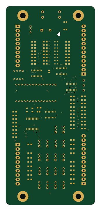 AVR/Arduino
Afterglow WHITESTAR 2.1
81 × 181.5 mm118 parts2LNo license32
Afterglow 3.0 Debug Hat
64.4 × 81 mm97 parts2LNo license32
Hat modder
64.4 × 81 mm28 parts2LNo license32
Afterglow 3.0 Pinbender Hat
64.4 × 81 mm8 parts2LNo license32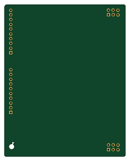
Hat template
64.4 × 81 mm4 parts2LNo license32
Similar boards
 AVR/Arduino
Redox keyboard
mattdibi
162.2 × 126.5 mm77 parts2LMIT2.0k AVR/Arduino
ModuleV450
stuartpittaway
30 × 61.4 mm39 parts2LCC-BY-NC-4.01.1k AVR/Arduino
V4
30 × 50 mm38 parts2LCC-BY-NC-4.01.1k AVR/Arduino
Discipline
coseyfannitutti
304.9 × 122.8 mm170 parts2LCC-BY-NC-4.01.0k AVR/Arduino
Megadesk
gcormier
41.7 × 32.2 mm23 parts2LGPL-3.0818 AVR/Arduino
Easyduino Atmega Nano
Hanqaqa
43.4 × 18 mm30 parts4LCERN-OHL-P-2.0746