
Afterglow

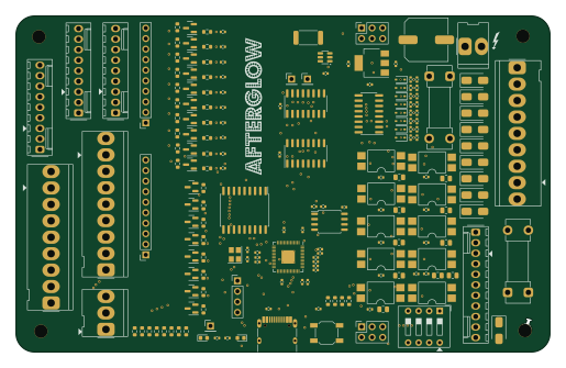
About the Afterglow PCB
Afterglow is an open source RP2040/RP2350 PCB design by bitfieldlabs, published on GitHub. It is a 2-layer board measuring 128.7 × 81 mm, with 196 components from 45 distinct parts.
Its main chip is the RP2040, from the RP2040/RP2350 family. Other key parts include the PC817, NCP1117-3.3_SOT223, ULN2803A, 74LS165 and W25Q32JVSS. By type, the board carries 96 resistors, 21 capacitors, 18 ICs, 18 transistors, 18 diodes and 15 connectors.
It belongs with the displays & leds and retro computing designs in this gallery.
From the project
Pinball retro afterglow
This is the newest generation of afterglow boards for the switched playfield lamps (not the GI), supporting WPC, Data East, System 11 and Stern Whitestar/S.A.M. games.
The new board is based on the RP2040 microprocessor. It is more robust than previous versions and it supports hats!
Components were chosen based on availability and price.
The connectors and some other parts are currently not included in the assembly files.
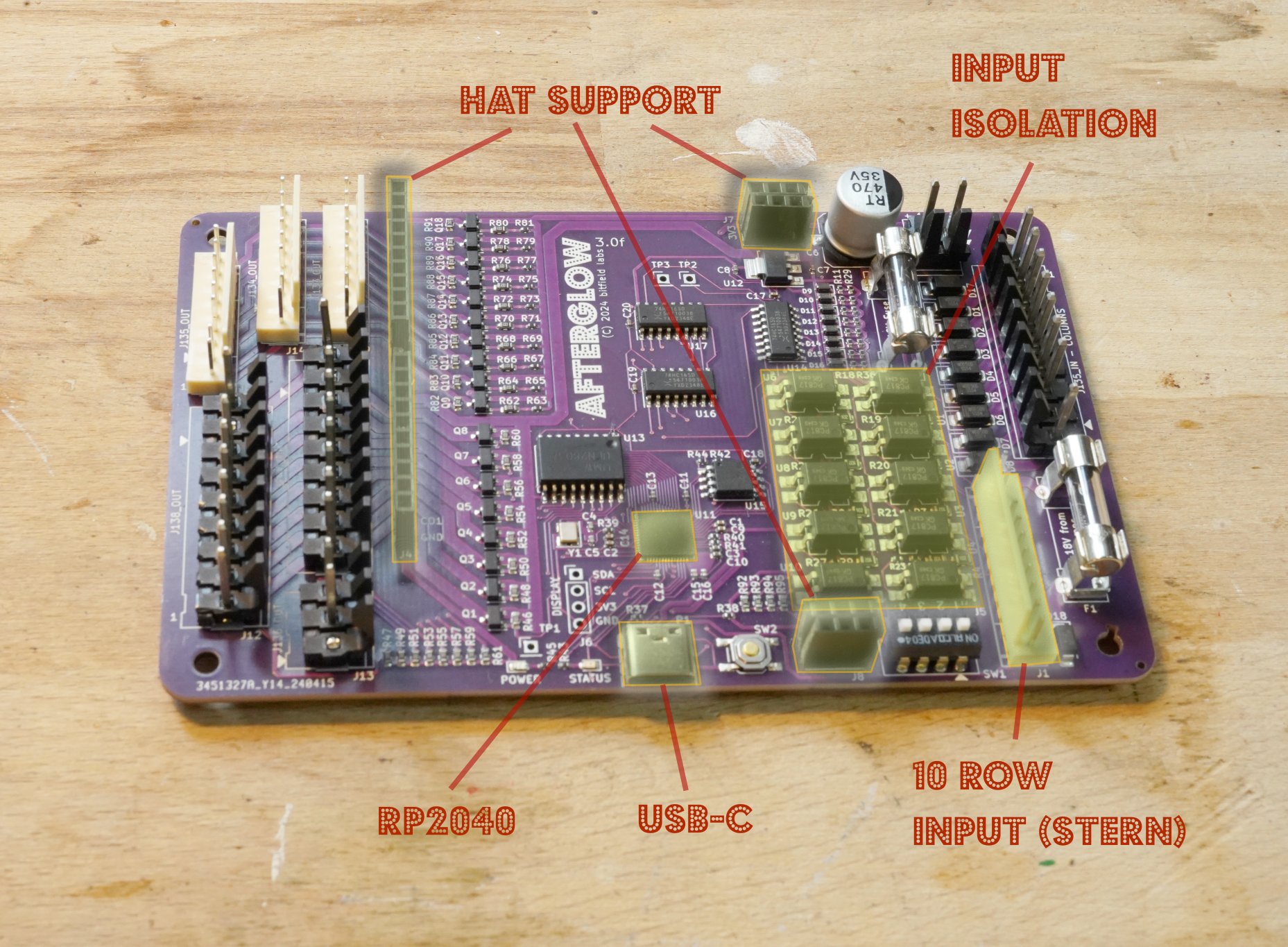
Main components on the Afterglow
Afterglow bill of materials (BOM)
196 components, 45 distinct parts — part numbers from the project's BOM.
| Qty | Part | Footprint | Refs |
|---|---|---|---|
| 10 | PC817 | SMDIP-4_W9.53mm | U1, U2, U3, U4, U5, U6, U7, U8 +2 |
| 1 | RP2040 | QFN-56-1EP_7x7mm_P0.4mm_EP3.2x3.2mm_ThermalVias | U11 |
| 1 | NCP1117-3.3_SOT223 | SOT-223-3_TabPin2 | U12 |
| 1 | ULN2803A | SOIC-18W_7.5x11.6mm_P1.27mm | U13 |
| 3 | 74LS165 | SOIC-16_3.9x9.9mm_P1.27mm | U14, U16, U17 |
| 1 | W25Q32JVSS | SOIC-8_5.23x5.23mm_P1.27mm | U15 |
| 1 | INA181A1 | SOT-23-6 | U18 |
| 8 | AO3401A | SOT-23 | Q1, Q2, Q3, Q4, Q5, Q6, Q7, Q8 |
| 10 | AO3400A | SOT-23 | Q9, Q10, Q11, Q12, Q13, Q14, Q15, Q16 +2 |
| 1 | CRYSTAL_GND24_SMALL Crystal_GND24_Small | Crystal_SMD_3225-4Pin_3.2x2.5mm | Y1 |
| 1 | J133_IN_R | Molex_KK-254_AE-6410-11A_1x11_P2.54mm_Vertical | J1 |
| 1 | J137_IN_C | Molex_KK-396_5273-09A_1x09_P3.96mm_Vertical | J2 |
| 1 | Conn_Power | Molex_KK-396_5273-02A_1x02_P3.96mm_Vertical | J3 |
| 2 | CONN_01X10_PIN Conn_01x10_Pin | PinSocket_1x10_P2.54mm_Vertical | J4, J5 |
| 1 | CONN_01X04_SOCKET Conn_01x04_Socket | PinHeader_1x04_P2.54mm_Vertical | J6 |
| 2 | CONN_02X03_ODD_EVEN Conn_02x03_Odd_Even | PinSocket_2x03_P2.54mm_Vertical | J7, J8 |
| 1 | J133_OUT_R | Molex_KK-254_AE-6410-09A_1x09_P2.54mm_Vertical | J9 |
| 1 | J137_OUT_C | Molex_KK-396_5273-09A_1x09_P3.96mm_Vertical | J10 |
| 1 | J134_OUT_R | Molex_KK-254_AE-6410-09A_1x09_P2.54mm_Vertical | J11 |
| 1 | J138_OUT_C | Molex_KK-396_5273-09A_1x09_P3.96mm_Vertical | J12 |
Show 25 more
| Qty | Part | Footprint | Refs |
|---|---|---|---|
| 1 | 136_OUT_C | Molex_KK-396_5273-03A_1x03_P3.96mm_Vertical | J13 |
| 1 | J135_OUT_R | Molex_KK-254_AE-6410-09A_1x09_P2.54mm_Vertical | J14 |
| 1 | USB_C_RECEPTACLE_USB2.0_14P USB_C_Receptacle_USB2.0_14P | USB_C_Receptacle_HRO_TYPE-C-31-M-12 | P1 |
| 2 | 5A SB | Fuseholder_Clip-5x20mm_Schurter_OG_Lateral_P15.00x5.00mm_D1.3mm_Horizontal | F1, F2 |
| 1 | CFG | SW_DIP_SPSTx04_Slide_9.78x12.34mm_W7.62mm_P2.54mm | SW1 |
| 1 | SW_Push | SW_SPST_SKQG_WithStem | SW2 |
| 3 | TestPoint | PinHeader_1x01_P2.54mm_Vertical | TP1, TP2, TP3 |
| 2 | LED | LED_0603_1608Metric | PWR_LED1, ST_LED1 |
| 10 | RB080 | D_SMA | D1, D2, D3, D4, D5, D6, D7, D8 +2 |
| 8 | 3.0V | D_SOD-323 | D9, D10, D11, D12, D13, D14, D15, D16 |
| 13 | 100N 100n | C_0402_1005Metric | C1, C2, C9, C11, C12, C13, C14, C15 +5 |
| 2 | 1u | C_0402_1005Metric | C3, C10 |
| 2 | 22P 22p | C_0402_1005Metric | C4, C5 |
| 1 | 470UF 470uF | C_Elec_10x10.2 | C6 |
| 2 | 1UF 1uF | C_0402_1005Metric | C7, C8 |
| 1 | 0.1 | C_0402_1005Metric | C18 |
| 10 | 1k | R_0805_2012Metric | R1, R2, R3, R4, R5, R6, R7, R8 +2 |
| 30 | 1k | R_0402_1005Metric | R11, R12, R13, R14, R15, R16, R17, R18 +22 |
| 2 | 5K1 5k1 | R_0402_1005Metric | R37, R38 |
| 2 | 27 | R_0402_1005Metric | R40, R41 |
| 11 | 10K 10k | R_0402_1005Metric | R44, R63, R65, R67, R69, R71, R73, R75 +3 |
| 8 | 2k | R_0603_1608Metric | R46, R48, R50, R52, R54, R56, R58, R60 |
| 22 | 10K 10k | R_0603_1608Metric | R47, R49, R51, R53, R55, R57, R59, R61 +14 |
| 10 | 220 | R_0603_1608Metric | R62, R64, R66, R68, R70, R72, R74, R76 +2 |
| 1 | 200MOHM 200mOhm | R_2512_6332Metric | R96 |
Afterglow design files
The KiCad project lives in the bitfieldlabs/afterglow repository on GitHub; these links point at the commit this page was built from.
Afterglow: common questions
What microcontroller does the Afterglow use?
The Afterglow is built around the RP2040, from the RP2040/RP2350 family.
How big is the Afterglow PCB?
The Afterglow measures 128.7 × 81 mm, has 2 copper layers and is 1.6 mm thick.
How many components are on the Afterglow?
196 components, from 45 distinct parts, with part numbers taken from the project's own BOM. The full bill of materials is listed on this page.
Where can I download the Afterglow design files?
From the bitfieldlabs/afterglow repository on GitHub, which has the KiCad layout, the schematic and the BOM; the links under Design files point to each one.
Can I use the Afterglow design in my own project?
The repository has no license, so all rights stay with bitfieldlabs. Use it as a reference, and ask the author before reusing the design.
Can I test firmware for the Afterglow without the hardware?
Yes. HardLabs builds a simulation of the board from its netlist and BOM, so you can run and debug RP2040/RP2350 firmware against it before you order a PCB.
More boards in afterglow
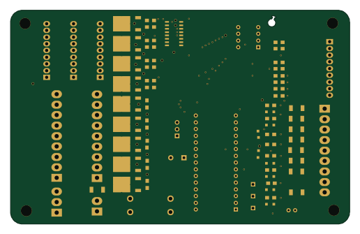
Afterglow 1.3
128.7 × 81 mm124 parts2LNo license32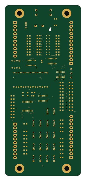 AVR/Arduino
Afterglow WHITESTAR 2.1
81 × 181.5 mm118 parts2LNo license32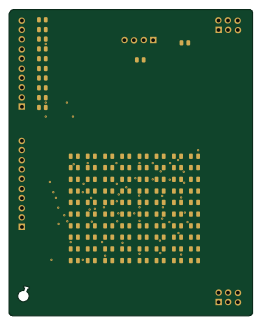
Afterglow 3.0 Debug Hat
64.4 × 81 mm97 parts2LNo license32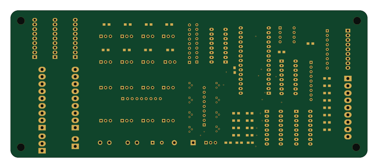 AVR/Arduino
Afterglow 1.1
193.5 × 80 mm78 parts2LNo license32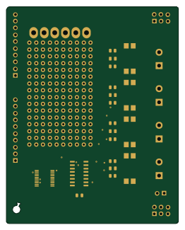
Hat modder
64.4 × 81 mm28 parts2LNo license32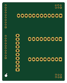
Afterglow 3.0 Pinbender Hat
64.4 × 81 mm8 parts2LNo license32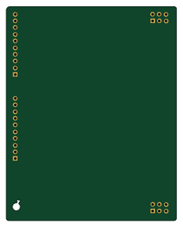
Hat template
64.4 × 81 mm4 parts2LNo license32
Similar boards
 RP2040/RP2350
Open Book Abridged Edition
joeycastillo
85 × 115 mm29 parts2LCC-BY-SA-4.08.1k RP2040/RP2350
Corne
foostan
277.2 × 107.5 mm164 parts2LCC-BY-4.07.7k RP2040/RP2350
Corne
277.2 × 107.5 mm164 parts2LCC-BY-4.07.7k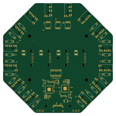 RP2040/RP2350
Hid remapper
jfedor2
100 × 100 mm124 parts2LMIT1.7k RP2040/RP2350
Open Source Smart Glasses
Mentra-Community
93 × 10.5 mm80 parts4LMIT1.2k RP2040/RP2350
MSA
30.5 × 138 mm61 parts2LMIT1.2k