
Antenna PCB v1

About the Antenna PCB v1
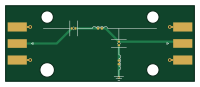
Antenna PCB v1 is an open source PCB design by buttonbugs, published on GitHub. It is a 2-layer board measuring 50 × 20 mm, with 6 components from 3 distinct parts.
By type, the board carries 2 connectors, 2 inductors and 2 capacitors.
It belongs with the sensors and rf & radio designs in this gallery.
From the project
This repository includes the payload codes for the UA AIAA Rocket Competition Team.
This repository includes the payload codes for the UA AIAA Rocket Competition Team.
Reference: Arduino Nano Every Full Pinout Diagram (Official)
Arduino footprints and symbols: Alarm-Siren/arduino-kicad-library
See https://jlcpcb.com/help/article/how-to-generate-gerber-and-drill-files-in-kicad-9
Antenna PCB v1 bill of materials (BOM)
6 components, 3 distinct parts.
| Qty | Part | Footprint | Refs |
|---|---|---|---|
| 2 | Conn_Coaxial_Power | SMA_Molex_73251-1153_EdgeMount_Horizontal | J1, J2 |
| 2 | L | L_0402_1005Metric | L1, L2 |
| 2 | C | C_0402_1005Metric | C1, C2 |
Antenna PCB v1 design files
The KiCad project lives in the buttonbugs/UA-AIAA-Payload-2026 repository on GitHub; these links point at the commit this page was built from.
Antenna PCB v1: common questions
How big is the Antenna PCB v1?
The Antenna PCB v1 measures 50 × 20 mm, has 2 copper layers and is 1.6 mm thick.
How many components are on the Antenna PCB v1?
6 components, from 3 distinct parts. The full bill of materials is listed on this page.
Where can I download the Antenna PCB v1 design files?
From the buttonbugs/UA-AIAA-Payload-2026 repository on GitHub, which has the KiCad layout and the schematic; the links under Design files point to each one.
Can I use the Antenna PCB v1 design in my own project?
The repository has no license, so all rights stay with buttonbugs. Use it as a reference, and ask the author before reusing the design.
More boards in UA-AIAA-Payload-2026
Similar boards

Sensor smd
scottbez1
40 × 20 mm5 parts2LApache-2.04.2k
Sensors
StuckAtPrototype
15.2 × 9 mm14 parts4LApache-2.03.8k
Microphone
Mentra-Community
5.5 × 6.1 mm6 parts2LMIT1.2k
TemperaturePCB PANEL
stuartpittaway
116 × 75.5 mm178 parts2LCC-BY-NC-4.01.1k
Pots
shanteacontrols
390 × 93 mm75 parts2LApache-2.0956
ButtonsLEDs
390 × 37 mm82 parts2LApache-2.0956