
Output

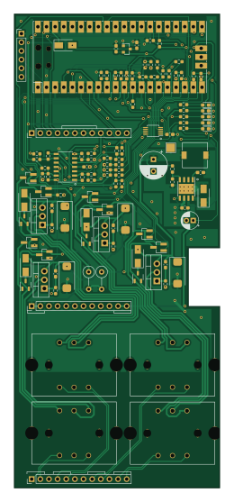
About the Output PCB
Output is an open source RP2040/RP2350 PCB design by CrashOverride85, published on GitHub under the GPL-3.0 license. It is a 2-layer board measuring 60.3 × 139.1 mm, with 116 components from 54 distinct parts.
Its main chip is the MAX3232EEAE+T, from the RP2040/RP2350 family. Other key parts include the TCA9534, BQ25601, TPS5430DDA and AT24C04CDRG. By type, the board carries 59 resistors, 16 capacitors, 15 diodes, 12 transistors, 5 ICs and 4 connectors.
From the project
4 channel EStim box inspired by the mk312bt, with Lua scripting support
The original ZC95 mk1 had the estim output stage on a separate PCB; that's been incorporated into the main board with the mkII. Whilst it was only ever intended to be used as a part of the ZC95, the output board could also be used from other projects, and there is an included Arduino library for it. So these are the (slightly tweaked) original build notes from that board, in case it's still of interest to anyone.
Main components on the Output
Output bill of materials (BOM)
116 components, 54 distinct parts — part numbers from the project's BOM.
| Qty | Part | Footprint | Refs |
|---|---|---|---|
| 1 | TCA9534 LM324 | SOIC-14_3.9x8.7mm_P1.27mm | U1 |
| 1 | BQ25601 MCP4728 | MSOP-10_3x3mm_P0.5mm | U2 |
| 1 | TPS5430DDA | TI_SO-PowerPAD-8_ThermalVias | U3 |
| 1 | MAX3232EEAE+T Pico | RPi_Pico_SMD_TH | U4 |
| 1 | AT24C04CDRG XC6206P332MR | SOT-23 | U5 |
| 1 | AO3401A AO3400A | SOT-23_Handsoldering | Q1 |
| 4 | AO3400A IRF9Z24NPBF | TO-220-3_Vertical | Q2, Q5, Q8, Q11 |
| 4 | IRF9Z24NPBF AO3400A | SOT-23_Handsoldering | Q3, Q6, Q9, Q12 |
| 3 | AO3400A | SOT-23_Handsoldering | Q4, Q7, Q10 |
| 1 | TRG1 MAIN_BOARD_IO | PinHeader_1x12_P2.54mm_Vertical | J1 |
| 1 | TRG1 MAIN_BOARD_POWER | PinHeader_1x12_P2.54mm_Vertical | J2 |
| 1 | CONN_02X04_ODD_EVEN MAIN_BOARD_FP | PinHeader_1x12_P2.54mm_Vertical | J3 |
| 1 | TRG1 Serial (3v3) | PinHeader_1x06_P2.54mm_Vertical | J4 |
| 4 | TRANSF5 | 42TL+U | TR1, TR2, TR3, TR4 |
| 1 | BZX584C3V6 SS34 | D_SMA | D1 |
| 1 | SS34 | D_SMA | D2 |
| 1 | C2986059 3v3 | LED_0603_1608Metric_Pad1.05x0.95mm_HandSolder | D3 |
| 1 | C2986059 5v | LED_0603_1608Metric_Pad1.05x0.95mm_HandSolder | D4 |
| 1 | 1SMA4734A 9v | LED_0603_1608Metric_Pad1.05x0.95mm_HandSolder | D5 |
| 1 | BZX584C3V6 12v | LED_0603_1608Metric_Pad1.05x0.95mm_HandSolder | D6 |
Show 34 more
| Qty | Part | Footprint | Refs |
|---|---|---|---|
| 1 | SMAJ13A OK | LED_0603_1608Metric_Pad1.05x0.95mm_HandSolder | D7 |
| 3 | BAV23CL SMAJ13A | D_SMA | D8, D10, D12 |
| 3 | SMAJ13A BAV23CL | SOT-23-3 | D9, D11, D15 |
| 1 | C2986059 BAV23CL | SOT-23-3 | D13 |
| 1 | C2986059 SMAJ13A | D_SMA | D14 |
| 1 | 1.5UH 15uH | L_7.3x7.3_H3.5 | L1 |
| 3 | 1UF 100nF | C_0603_1608Metric_Pad1.08x0.95mm_HandSolder | C1, C2, C5 |
| 3 | 100NF 100nF | C_0603_1608Metric_Pad1.08x0.95mm_HandSolder | C3, C4, C6 |
| 1 | 100NF 10nF | C_0603_1608Metric_Pad1.08x0.95mm_HandSolder | C7 |
| 1 | 100NF 10uF | C_0603_1608Metric_Pad1.08x0.95mm_HandSolder | C8 |
| 1 | 10UF 220uF | CP_Radial_D8.0mm_P3.50mm | C9 |
| 1 | 100NF 1uF | C_0603_1608Metric_Pad1.08x0.95mm_HandSolder | C10 |
| 1 | 220UF 1uF | C_0603_1608Metric_Pad1.08x0.95mm_HandSolder | C11 |
| 3 | 100NF 220uF | CP_EIA-7343-43_Kemet-X_Pad2.25x2.55mm_HandSolder | C12, C13, C15 |
| 1 | 220UF 220uF | CP_EIA-7343-43_Kemet-X_Pad2.25x2.55mm_HandSolder | C14 |
| 1 | 100NF 100uF | CP_Radial_D5.0mm_P2.00mm | C16 |
| 2 | 10K 0.5R | R_Axial_DIN0309_L9.0mm_D3.2mm_P5.08mm_Vertical | R1, R26 |
| 9 | 10K 100k | R_0603_1608Metric_Pad0.98x0.95mm_HandSolder | R2, R4, R15, R23, R24, R25, R33, R38 +1 |
| 6 | 10K 10k | R_0603_1608Metric_Pad0.98x0.95mm_HandSolder | R3, R11, R18, R43, R49, R57 |
| 9 | 100R 100k | R_0603_1608Metric_Pad0.98x0.95mm_HandSolder | R5, R8, R16, R19, R21, R27, R29, R30 +1 |
| 4 | 100R 150k | R_0603_1608Metric_Pad0.98x0.95mm_HandSolder | R6, R9, R20, R31 |
| 5 | 100R 10k | R_0603_1608Metric_Pad0.98x0.95mm_HandSolder | R7, R14, R22, R28, R32 |
| 1 | 2K2 100k | R_0603_1608Metric_Pad0.98x0.95mm_HandSolder | R10 |
| 5 | 100K 100k | R_0603_1608Metric_Pad0.98x0.95mm_HandSolder | R12, R13, R37, R40, R48 |
| 2 | 10K 150k | R_0603_1608Metric_Pad0.98x0.95mm_HandSolder | R17, R34 |
| 1 | 0.5R 10k | R_0603_1608Metric_Pad0.98x0.95mm_HandSolder | R36 |
| 3 | 100K 10k | R_0603_1608Metric_Pad0.98x0.95mm_HandSolder | R39, R47, R56 |
| 3 | 150K 100k | R_0603_1608Metric_Pad0.98x0.95mm_HandSolder | R41, R44, R52 |
| 2 | 100K 150k | R_0603_1608Metric_Pad0.98x0.95mm_HandSolder | R42, R45 |
| 2 | 100K 4k7 | R_0603_1608Metric_Pad0.98x0.95mm_HandSolder | R50, R51 |
| 2 | 100K 1.5k | R_0603_1608Metric_Pad0.98x0.95mm_HandSolder | R53, R58 |
| 1 | 10K 1.5k | R_0603_1608Metric_Pad0.98x0.95mm_HandSolder | R54 |
| 1 | 150K 4k7 | R_0603_1608Metric_Pad0.98x0.95mm_HandSolder | R55 |
| 1 | 100K 680 | R_0603_1608Metric_Pad0.98x0.95mm_HandSolder | R59 |
Output design files
The KiCad project lives in the CrashOverride85/zc95 repository on GitHub; these links point at the commit this page was built from.
Output: common questions
What microcontroller does the Output use?
The Output is built around the MAX3232EEAE+T, from the RP2040/RP2350 family.
How big is the Output PCB?
The Output measures 60.3 × 139.1 mm, has 2 copper layers and is 1.6 mm thick.
How many components are on the Output?
116 components, from 54 distinct parts, with part numbers taken from the project's own BOM. The full bill of materials is listed on this page.
Where can I download the Output design files?
From the CrashOverride85/zc95 repository on GitHub, which has the KiCad layout, the schematic and the BOM; the links under Design files point to each one.
Can I use the Output design in my own project?
Yes, under the terms of its GPL-3.0 license, which CrashOverride85 chose for the repository.
Can I test firmware for the Output without the hardware?
Yes. HardLabs builds a simulation of the board from its netlist and BOM, so you can run and debug RP2040/RP2350 firmware against it before you order a PCB.
More boards in zc95
Similar boards
 RP2040/RP2350
OSO-BOOK-C1
joeycastillo
85 × 115 mm29 parts2LCC-BY-SA-4.08.1k RP2040/RP2350
Corne cherry
foostan
277.2 × 107.5 mm164 parts2LCC-BY-4.07.7k RP2040/RP2350
Corne chocolate
277.2 × 107.5 mm164 parts2LCC-BY-4.07.7k RP2040/RP2350
Jitx design
gusmanb
55.5 × 65 mm26 parts4LGPL-3.05.0k RP2040/RP2350
LogicAnalyzer
57 × 55.2 mm6 parts2LGPL-3.05.0k RP2040/RP2350
Main
google
98 × 71 mm102 parts2LApache-2.02.9k