
Dimmer esp v1 main

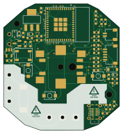
About the Dimmer esp v1 main PCB
Dimmer esp v1 main is an open source ESP32 PCB design by dagroe, published on GitHub under the MIT license. It is a 4-layer board measuring 44 × 48.1 mm, with 53 components from 30 distinct parts.
Its main chip is the ESP32-C6-MINI-1-N4, from the ESP32 family. Other key parts include the PEC11S-929K-S0015, SGM2212-3.3XKC3G/TR, TYPE-C 16PLT-H10.0 and SN74LV1T125DBVR. By type, the board carries 20 resistors, 12 capacitors, 6 diodes, 5 ICs, 3 connectors and 3 switches.
It belongs with the iot & wireless designs in this gallery.
From the project
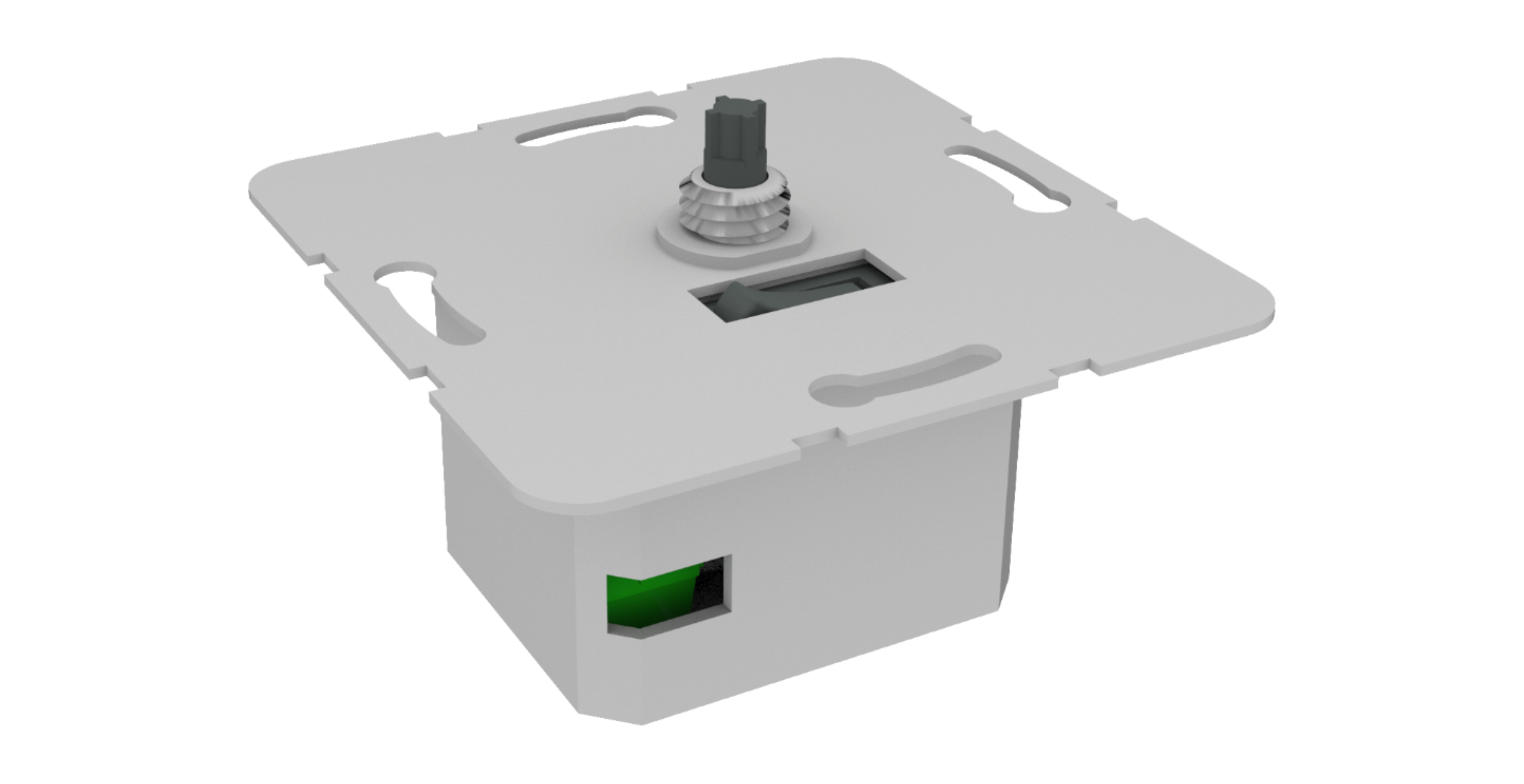
a rotary dimmer switch
Also nice to have: be extendable, e.g. easily add multiple dimmer switches or push buttons in multi frames ✅ allow for a second rotary input by rotating the knob while pushing it (e.g. to change color temperature or scenes) — implemented: push + rotate changes color temperature ✅ feature an integrated 230V (or 110V) mechanical switch to switch power of the connected lamp socket (e.g. for emergencies or to reset the lamp when replacing classic wall switches) — implemented: on-board relay + dedicated button be affordable
Main components on the Dimmer esp v1 main
Dimmer esp v1 main bill of materials (BOM)
53 components, 30 distinct parts.
| Qty | Part | Footprint | Refs |
|---|---|---|---|
| 1 | PEC11S-929K-S0015 | PEC11S929KS0015 | IC1 |
| 1 | SGM2212-3.3XKC3G/TR SGMICRO(圣邦微) | SOT-223-3_L6.5-W3.4-P2.30-LS7.0-BR | U1 |
| 1 | TYPE-C 16PLT-H10.0 USB TYPE-C 16PLT-H10.0 SHOU HAN(首韩) | TYPE-C-SMD_USB4120-03-C | U2 |
| 1 | SN74LV1T125DBVR | SOT-23-5 | U3 |
| 1 | ESP32-C6-MINI-1-N4 ESP32-C6-MINI ESPRESSIF(乐鑫) | WIFIM-SMD_61P-L16.6-W13.2-P0.80-ESP32-C6-MINI-1-N4 | U4 |
| 1 | BC817-40,215 BC817 | SOT-23 | Q1 |
| 1 | 1715734 Screw_Terminal_01x03 | TerminalBlock_Phoenix_MKDS-1,5-3-5.08_1x03_P5.08mm_Horizontal | J1 |
| 1 | SM05B-SRSS-TB(LF)(SN) SM05B-SRSS-TB_LF__SN_ | JST_SH_SM05B-SRSS-TB_1x05-1MP_P1.00mm_Horizontal | J2 |
| 1 | SM02B-SRSS-TB(LF)(SN) Conn_01x02 | JST_SH_SM02B-SRSS-TB_1x02-1MP_P1.00mm_Horizontal | J3 |
| 1 | 0443.500DR Fuse 230V 500mA Slow | 0443.500DR | F1 |
| 1 | FTR-LYCA005Y | FTRLYCA024Y | K1 |
| 1 | IRM-02-5S | Converter_ACDC_MeanWell_IRM-02-xx_SMD | PS1 |
| 1 | TS-1088-AR02016 Commission XUNPU(讯普) | SW-SMD_L3.9-W3.0-P4.45 | SW1 |
| 1 | TS-1088-AR02016 Toggle XUNPU(讯普) | SW-SMD_L3.9-W3.0-P4.45 | SW2 |
| 1 | TS-1088-AR02016 Reset XUNPU(讯普) | SW-SMD_L3.9-W3.0-P4.45 | SW3 |
| 1 | 1N4148WS | D_SOD-323 | D1 |
| 3 | BNLESD5D5.0CT1G LESD5D5.0CT1G | D_SOD-523 | D2, D3, D5 |
| 1 | 1N5819HW-7-F | D_SOD-123 | D4 |
| 1 | XL-5050RGBC-2812B LED: WS2812B_5050 | LED_WS2812B_PLCC4_5.0x5.0mm_P3.2mm | D6 |
| 4 | 0603B103K500NT 0.01u | C_0603_1608Metric | C1, C2, C11, C12 |
Show 10 more
| Qty | Part | Footprint | Refs |
|---|---|---|---|
| 2 | CT41G-0603-2X1-50V-0.1uF-K(N) 0.1uF/50V(10%) | C_0603_1608Metric | C3, C5 |
| 3 | MVK25V10M4*5 4.0TP 10uF/25V(20%) | C_Elec_4x5.4 | C4, C6, C8 |
| 1 | CL10A105KB8NNNC 1u | C_0603_1608Metric | C7 |
| 1 | 0.1uF/50V(10%) | C_0603_1608Metric | C9 |
| 1 | CC0603KRX7R9BB104 0.1uF | C_0603_1608Metric | C10 |
| 15 | 0603WAF1002T5E 10k | R_0603_1608Metric | R1, R2, R3, R4, R5, R6, R8, R9 +7 |
| 1 | 0603WAF1001T5E 1k | R_0603_1608Metric | R7 |
| 2 | 0603WAF5101T5E 5.1k | R_0603_1608Metric | R10, R11 |
| 1 | 0603WAF3301T5E 3.3k | R_0603_1608Metric | R17 |
| 1 | 0603WAF3300T5E 330 | R_0603_1608Metric | R20 |
Dimmer esp v1 main design files
The KiCad project lives in the dagroe/zigbee-rotary-dimmer-switch repository on GitHub; these links point at the commit this page was built from.
Dimmer esp v1 main: common questions
What microcontroller does the Dimmer esp v1 main use?
The Dimmer esp v1 main is built around the ESP32-C6-MINI-1-N4, from the ESP32 family.
How big is the Dimmer esp v1 main PCB?
The Dimmer esp v1 main measures 44 × 48.1 mm, has 4 copper layers and is 1.6 mm thick.
How many components are on the Dimmer esp v1 main?
53 components, from 30 distinct parts. The full bill of materials is listed on this page.
Where can I download the Dimmer esp v1 main design files?
From the dagroe/zigbee-rotary-dimmer-switch repository on GitHub, which has the KiCad layout and the schematic; the links under Design files point to each one.
Can I use the Dimmer esp v1 main design in my own project?
Yes, under the terms of its MIT license, which dagroe chose for the repository.
Can I test firmware for the Dimmer esp v1 main without the hardware?
Yes. HardLabs builds a simulation of the board from its netlist and BOM, so you can run and debug ESP32 firmware against it before you order a PCB.
More boards in zigbee-rotary-dimmer-switch
Similar boards
 ESP32
ESP32Open Book Abridged Edition
joeycastillo
85 × 115 mm65 parts2LCC-BY-SA-4.08.1k ESP32
ESP32Badge
atopile
56.3 × 39 mm239 parts4LMIT4.0k ESP32
ESP32Esp32 minimal
36.2 × 26.8 mm20 parts2LMIT4.0k ESP32
ESP32Racer
StuckAtPrototype
36 × 50.2 mm70 parts4LApache-2.03.8k ESP32
ESP32Controller
29 × 74 mm58 parts4LApache-2.03.8k ESP32
ESP32Bitaxe
skot
56.5 × 99.8 mm86 parts4LCERN-OHL-S-2.01.4k