
RoboBoat PCB 2

About the RoboBoat PCB 2
RoboBoat PCB 2 is an open source RP2040/RP2350 PCB design by danielwilczak101, published on GitHub. It is a 2-layer board measuring 42.8 × 39 mm, with 125 components from 35 distinct parts.
Its main chip is the RC Pico, from the RP2040/RP2350 family. Other key parts include the Level Shifter, Autonomous Pico and 12V TO 5V LM2596 (3A). By type, the board carries 35 resistors, 29 connectors, 23 diodes, 20 transistors, 11 relays and 5 ICs.
From the project
ERAU and EPPL collaberation to create an autonomous drift cart that drives around campus.
Main components on the RoboBoat PCB 2
RoboBoat PCB 2 bill of materials (BOM)
125 components, 35 distinct parts — part numbers from the project's BOM.
| Qty | Part | Footprint | Refs |
|---|---|---|---|
| 2 | Level Shifter | CONV_BOB-12009 | U1, U8 |
| 1 | RC Pico | RPi_Pico_SMD_TH | U3 |
| 1 | Autonomous Pico | RPi_Pico_SMD_TH | U4 |
| 1 | 12V TO 5V LM2596 (3A) | DCDC_StepDown_LM2596 | U6 |
| 10 | ~ | DIP762W50P254L650H458Q4B | Q1, Q2, Q3, Q4, Q5, Q11, Q12, Q13 +2 |
| 10 | ~ | TO-92_Inline | Q6, Q7, Q8, Q9, Q10, Q15, Q16, Q17 +2 |
| 1 | RC_PICO_Power/Coms | PinSocket_2x06_P2.54mm_Vertical | J1 |
| 1 | FrontServoOutput | PinHeader_1x03_P2.54mm_Vertical | J2 |
| 1 | RC Reciever | PinHeader_1x04_P2.54mm_Vertical | J3 |
| 1 | TurretServoOutput_1 | PinHeader_1x03_P2.54mm_Vertical | J4 |
| 1 | LED | PinHeader_1x03_P2.54mm_Vertical | J5 |
| 1 | SCREW_TERMINAL_01X02 TurretServoOutput_2 | PinHeader_1x03_P2.54mm_Vertical | J6 |
| 1 | 8P8C Auto_PICO_Power/Coms | PinSocket_2x06_P2.54mm_Vertical | J7 |
| 1 | 8P8C BackServoOutput | PinHeader_1x03_P2.54mm_Vertical | J8 |
| 1 | FrontMotorOutput | PinSocket_2x06_P2.54mm_Vertical | J9 |
| 1 | BackMotorOutput | PinSocket_2x06_P2.54mm_Vertical | J10 |
| 10 | ~ | PinHeader_1x02_P2.54mm_Vertical | J11, J12, J13, J14, J15, J16, J17, J18 +2 |
| 2 | 24V IN | AMASS_XT60PW-M | J20, J21 |
| 2 | 24V Out | AMASS_XT60PW-M | J22, J23 |
| 1 | 24V Out To DC-DC Converter | AMASS_XT60PW-M | J24 |
Show 15 more
| Qty | Part | Footprint | Refs |
|---|---|---|---|
| 1 | 12V IN | AMASS_XT60PW-M | J25 |
| 1 | 12V OUT Xavier | AMASS_XT60PW-M | J26 |
| 1 | 12V OUT Router | AMASS_XT60PW-M | J27 |
| 1 | 12V OUT WaterPump | AMASS_XT60PW-M | J28 |
| 2 | 3555-2 | FUSE_3555-2 | F1, F2 |
| 10 | ~ | Relay_SPDT_Finder_36.11 | K1, K2, K3, K4, K5, K6, K7, K8 +2 |
| 1 | 24V 80A E-Stop Relay | JD2912-1H-24VDC 80A 28VDC | K10 |
| 10 | LED2 | LED_0402_1005Metric | D1, D2, D3, D4, D8, D14, D15, D16 +2 |
| 3 | LED | LED_0402_1005Metric | D5, D6, D7 |
| 10 | ~ | D_1210_3225Metric | D9, D10, D11, D12, D13, D18, D19, D20 +2 |
| 20 | 1K | R_0805_2012Metric | R1, R2, R3, R4, R5, R9, R10, R11 +12 |
| 3 | 300 | R_0603_1608Metric | R6, R7, R8 |
| 1 | 10k | R_0805_2012Metric | R22 |
| 1 | 15k | R_0805_2012Metric | R23 |
| 10 | 100K | R_0805_2012Metric | R24, R25, R26, R27, R28, R29, R30, R31 +2 |
RoboBoat PCB 2 design files
The KiCad project lives in the danielwilczak101/EasyDrift repository on GitHub; these links point at the commit this page was built from.
RoboBoat PCB 2: common questions
What microcontroller does the RoboBoat PCB 2 use?
The RoboBoat PCB 2 is built around the RC Pico, from the RP2040/RP2350 family.
How big is the RoboBoat PCB 2?
The RoboBoat PCB 2 measures 42.8 × 39 mm, has 2 copper layers and is 1.6 mm thick.
How many components are on the RoboBoat PCB 2?
125 components, from 35 distinct parts, with part numbers taken from the project's own BOM. The full bill of materials is listed on this page.
Where can I download the RoboBoat PCB 2 design files?
From the danielwilczak101/EasyDrift repository on GitHub, which has the KiCad layout and the BOM; the links under Design files point to each one.
Can I use the RoboBoat PCB 2 design in my own project?
The repository has no license, so all rights stay with danielwilczak101. Use it as a reference, and ask the author before reusing the design.
Can I test firmware for the RoboBoat PCB 2 without the hardware?
Yes. HardLabs builds a simulation of the board from its netlist and BOM, so you can run and debug RP2040/RP2350 firmware against it before you order a PCB.
More boards in EasyDrift
 RP2040/RP2350
Linear Actuator
42.8 × 39 mm127 parts2LNo license0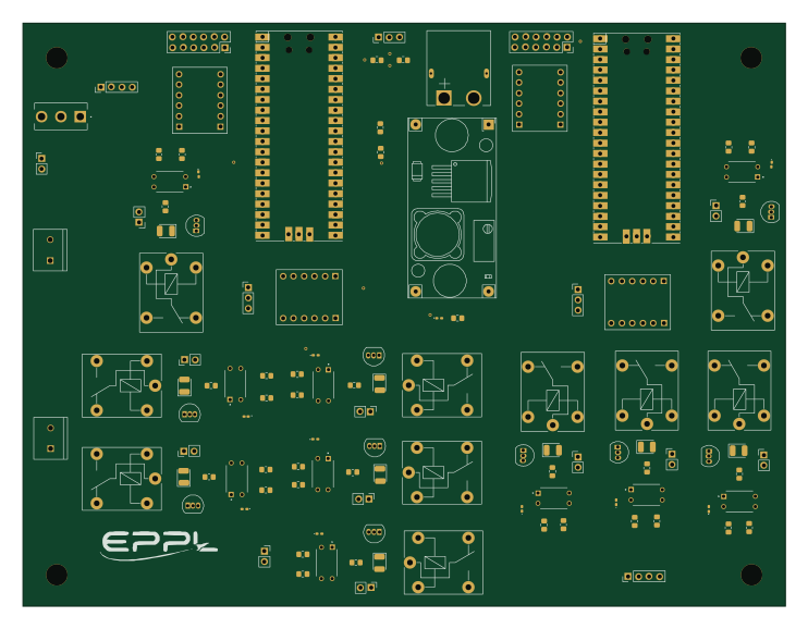 RP2040/RP2350
Autonomous Drift Cart
185.2 × 141.7 mm116 parts2LNo license0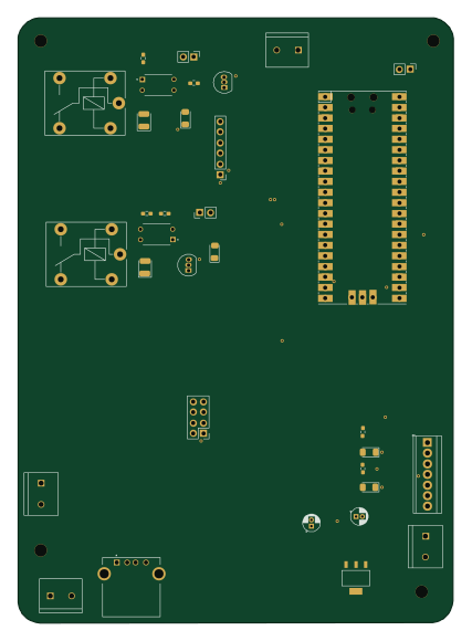 RP2040/RP2350
CC PCB V1
104.2 × 144.9 mm33 parts2LNo license0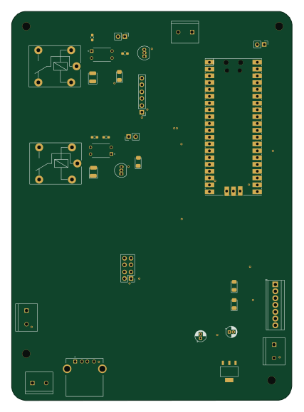 RP2040/RP2350
CC PCB V1 3
104.2 × 144.9 mm30 parts2LNo license0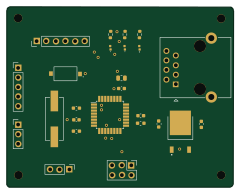 AVR/Arduino
Stepper Motor
60 × 47.8 mm23 parts2LNo license0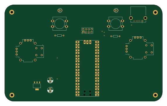 RP2040/RP2350
Controller V1
142.9 × 87.6 mm14 parts2LNo license0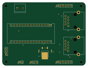 AVR/Arduino
Main Controller PCB V0.1
75.9 × 57.4 mm12 parts2LNo license0
Similar boards
 RP2040/RP2350
Open Book Abridged Edition
joeycastillo
85 × 115 mm29 parts2LCC-BY-SA-4.08.1k RP2040/RP2350
Corne
foostan
277.2 × 107.5 mm164 parts2LCC-BY-4.07.7k RP2040/RP2350
Corne
277.2 × 107.5 mm164 parts2LCC-BY-4.07.7k RP2040/RP2350
LogicAnalyzer
gusmanb
57 × 55.2 mm6 parts2LGPL-3.05.0k RP2040/RP2350
Jitx design
55.5 × 65 mm26 parts4LGPL-3.05.0k RP2040/RP2350
Main
google
98 × 71 mm102 parts2LApache-2.02.9k