
NEMA23-Stepper-Controller

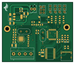
About the NEMA23-Stepper-Controller PCB
NEMA23-Stepper-Controller is an open source AVR/Arduino PCB design by Davey09, published on GitHub. It is a 2-layer board measuring 61.2 × 52.1 mm, with 60 components from 30 distinct parts.
Its main chip is the ATMEGA328-A, from the AVR/Arduino family. Other key parts include the NCP1117-5.0_SOT223, FT232RL and TMC2209-LA. By type, the board carries 22 capacitors, 17 resistors, 8 connectors, 6 diodes, 4 ICs and 2 crystals.
It belongs with the robotics & motion, usb & debug tools and power & battery designs in this gallery.
From the project
Arduino-compatible 12 V stepper motor controller PCB — ATmega328, TMC2209 silent driver, USB-C (FT232RL). KiCad 9 sources, Gerbers, BOM and 3D renders.
A compact, single-axis 12 V bipolar stepper motor controller that combines an ATmega328 microcontroller (Arduino Uno–compatible), a Trinamic TMC2209 silent stepper driver and an FT232RL USB-C serial interface on one 61 × 52 mm two-layer board.
The board is intended as a self-contained joint controller: one board drives one motor, and several boards can be networked over UART to coordinate a multi-axis machine such as a robotic arm. It was designed as the joint electronics for the 5-DOF Cycloidal Drive Robotic Arm.
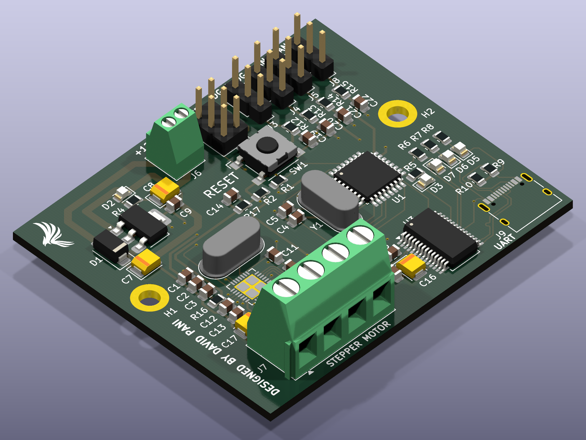
Main components on the NEMA23-Stepper-Controller
NEMA23-Stepper-Controller bill of materials (BOM)
60 components, 30 distinct parts — part numbers from the project's BOM.
| Qty | Part | Footprint | Refs |
|---|---|---|---|
| 1 | ATMEGA328-A ATmega328-A | TQFP-32_7x7mm_P0.8mm | U1 |
| 1 | NCP1117-5.0_SOT223 | SOT-223-3_TabPin2 | U2 |
| 1 | FT232RL | SSOP-28_5.3x10.2mm_P0.65mm | U3 |
| 1 | TMC2209-LA | VQFN-28-1EP_5x5mm_P0.5mm_EP3.7x3.7mm_ThermalVias | U5 |
| 2 | 16MHZ 16MHz | Crystal_HC49-4H_Vertical | Y1, Y2 |
| 1 | ISP | PinHeader_2x03_P2.54mm_Vertical | J2 |
| 1 | DIGITAL_1 | PinHeader_1x03_P2.54mm_Vertical | J3 |
| 1 | DIGITAL_2 | PinHeader_1x03_P2.54mm_Vertical | J4 |
| 1 | ANALOG_1 | PinHeader_1x03_P2.54mm_Vertical | J5 |
| 1 | Power input | TerminalBlock_Phoenix_MPT-0,5-2-2.54_1x02_P2.54mm_Horizontal | J6 |
| 1 | Stepper_motor | TerminalBlock_Phoenix_MKDS-1,5-4_1x04_P5.00mm_Horizontal | J7 |
| 1 | ANALOG_2 | PinHeader_1x03_P2.54mm_Vertical | J8 |
| 1 | USB_C_RECEPTACLE_USB2.0_16P USB_C_Receptacle_USB2.0_16P | USB_C_Receptacle_XKB_U262-16XN-4BVC11 | J9 |
| 1 | SW_Push | SW_SPST_Omron_B3FS-100xP | SW1 |
| 1 | US1G | D_SMA | D1 |
| 2 | LED | LED_0805_2012Metric | D2, D3 |
| 1 | RX | LED_0805_2012Metric | D5 |
| 1 | PWR | LED_0805_2012Metric | D6 |
| 1 | TX | LED_0805_2012Metric | D7 |
| 11 | 100NF 100nF | C_0805_2012Metric | C1, C2, C3, C6, C9, C10, C11, C12 +3 |
Show 10 more
| Qty | Part | Footprint | Refs |
|---|---|---|---|
| 2 | 22PF 22pF | C_0805_2012Metric | C4, C5 |
| 4 | 4.7UF 4.7uF | CP_EIA-3528-15_AVX-H | C7, C8, C16, C17 |
| 1 | 100μF | C_0805_2012Metric | C13 |
| 4 | 160NF 160nF | C_0805_2012Metric | C19, C20, C21, C22 |
| 3 | 10kΩ | R_0805_2012Metric | R1, R2, R16 |
| 2 | 0.11Ω | R_0805_2012Metric | R3, R11 |
| 6 | 1kΩ | R_0805_2012Metric | R4, R5, R12, R13, R14, R15 |
| 3 | 300Ω | R_0805_2012Metric | R6, R7, R8 |
| 2 | 5.1kΩ | R_0805_2012Metric | R9, R10 |
| 1 | 6.2kΩ | R_0805_2012Metric | R17 |
NEMA23-Stepper-Controller design files
The KiCad project lives in the Davey09/NEMA23-Stepper-Controller-PCB repository on GitHub; these links point at the commit this page was built from.
NEMA23-Stepper-Controller: common questions
What microcontroller does the NEMA23-Stepper-Controller use?
The NEMA23-Stepper-Controller is built around the ATMEGA328-A, from the AVR/Arduino family.
How big is the NEMA23-Stepper-Controller PCB?
The NEMA23-Stepper-Controller measures 61.2 × 52.1 mm, has 2 copper layers and is 1.6 mm thick.
How many components are on the NEMA23-Stepper-Controller?
60 components, from 30 distinct parts, with part numbers taken from the project's own BOM. The full bill of materials is listed on this page.
Where can I download the NEMA23-Stepper-Controller design files?
From the Davey09/NEMA23-Stepper-Controller-PCB repository on GitHub, which has the KiCad layout, the schematic and the BOM; the links under Design files point to each one.
Can I use the NEMA23-Stepper-Controller design in my own project?
The repository has no license, so all rights stay with Davey09. Use it as a reference, and ask the author before reusing the design.
Can I test firmware for the NEMA23-Stepper-Controller without the hardware?
Yes. HardLabs builds a simulation of the board from its netlist and BOM, so you can run and debug AVR/Arduino firmware against it before you order a PCB.
Similar boards
 AVR/Arduino
Magspoof
samyk
35 × 29 mm11 parts2LNo license4.2k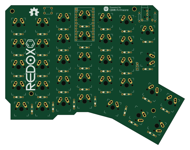 AVR/Arduino
Redox keyboard
mattdibi
162.2 × 126.5 mm77 parts2LMIT2.0k AVR/Arduino
Labrador
espotek-org
36.8 × 34.7 mm75 parts2LNo license1.2k AVR/Arduino
V4
stuartpittaway
30 × 50 mm38 parts2LCC-BY-NC-4.01.1k AVR/Arduino
ModuleV450
30 × 61.4 mm39 parts2LCC-BY-NC-4.01.1k AVR/Arduino
Discipline
coseyfannitutti
304.9 × 122.8 mm170 parts2LCC-BY-NC-4.01.0k